Gigaset
28.10.96 1054TIT.FM Gigaset 1054 A30852-X954-B101-1-7619
Table of Contents
Outgoing Calls
Operation with Standard Mobile Unit Standard Settings
Switching Features
Incoming Calls
Lock
System Settings
Mobile Unit Settings
Operation with Comfort Mobile Unit Using the Menu
Operation with Auxiliary Device Outgoing Calls
Switching Functions
Telephone Book
Charges, Call Length
Operation on Telephone Systems Standard Mobile Unit
Using the Features
Acoustic Signalling
Multicell System
Table of Contents
About the Operating Instructions
Introduction
About this Device
Rear
Overview Figures
Front Registration Key to register the mobile units
Comfort Mobile Unit 1000C
Standard Mobile Unit 1000S
Important Tips
Safety Precautions
Putting Into Service
Recommendation
Step by Step Instructions
Special Accessories
Putting Into Service Base Station Gigaset
Contents of Package
Installation Site / Selection of the Mounting Site
Range
Mounting / Connecting the Base Station
Connections for Gigaset
Specifications for Wall Mounting
Status of the Base Station Upon Delivery
Connection Options at the Base Station
Tips for Individuals with Hearing Aids
Putting Into Service Mobile Unit
Installing and Charging the Rechargeable Batteries
Installing the batteries in the mobile unit
Mobile Unit Gigaset 1000S Gigaset 1000C
Mounting the Carrying Clip on the Mobile Unit
UUPzAH
Putting Into Service Standard Mobile Unit
Symbol Explanation
Symbols Explanation
On OFF, Lock Status
Zzzz
You will hear the key acknowledg- ment tone
Switching the Status Switching from on status
Switching from OFF status
Switching from Lock status
12345678
012
Viewing and Setting the Dialing Mode
Determining the Dialing Mode of Your Telephone
Graphic Explanation
Putting Into Service Comfort Mobile Unit
Display
OFF
ON, OFF, Lock Status
You will hear the key acknowledgment tone
Registration key
Viewing Your Own Internal Number
At initialization, your telephone is set for tone dialing
Determining the Dialing Mode of Your Telephone Connection
Can be connected Internal station no Register on system as
Putting Into Service Non-Cordless Devices
Connecting Non-Cordless Devices other than telephones
Connection Jacks
KL1/KL2
Connection Points for the TFE Adapter Box
Please note for door interphone adapter TFE/V
Connection Examples for Door Interphones via TFE
Tip
Every digit entered replaces one of the first 4 dashes
Operation with Standard Mobile Unit Standard Settings
Saving / Changing the System Code
Be sure to note this
Enter the previously-set mobile unit
Procedure is complete New mobile unit PIN is stored
Enter / Change Mobile Unit PIN
Push the 8 key
Pitch
Setting Tone Ring of the Mobile Unit Volume
To activate, push the 1 key status at initialization
Current settings are shown
012 N3 2
Activate / Deactivate Automatic Line Seizure
Every digit entered replaces one dash on the screen
Activate / Deactivate Call Pickup
Operation with Standard Mobile Unit Incoming Calls
Call Pickup
CD F
123456
Automatic line seizure is not pro- grammed
External Dialing, Using Dialpad
1123456
Operation with Standard Mobile Unit Outgoing Calls
Automatic Line Seizure Not Programmed
Using the Dialpad for External Dialing as En-Bloc Dialing
123456 0123456
Automatic Line Seizure Programmed
Number Redial as En-Bloc Dialing
112345678
12345678 34567890 034567890
Number Redial
Internal Dialing with Collective Call
236
Internal Call to Another Mobile Unit or Auxiliary Device
Phone number stored at that memory location is dialed
Dialing Speed Dial Numbers
Finding and Dialing Speed Dial Numbers
Direct Dial of Speed Dial Numbers
Station number of the internal sta- tion and INT blink
Operation with Standard Mobile Unit During the Call
Placing a Call on Hold
Placing an Internal Call on Hold
Operation with Standard Mobile Unit During a Call
Dialing mode is changed to tone dialing
Temporary Switch to Tone Dialing
Confirm Stored Telephone Number
333333
Operation with Standard Mobile Unit Speed Dial
Speed Dial Numbers Storing, Viewing or Changing
Delete Speed Dial Numbers
Operation with Standard Mobile Unit Speed Dialing
0123
Operation with Standard Mobile Unit Switching Features
Or Terminate External Consultation
234567890
External Consultation
2345678
Way Conference from Within an External Consultation Call
Way Conference
Way Conference from Within an Internal Consultation Call
Terminate 3-Way Conference
Deactivate Internal Call Forwarding
91 7
Activate Internal Call Forwarding
Connection with the Door Interphone
Operation with Standard Mobile UnitSwitching Features
1or 0 To activate, push the 1 key initialization status
00-00
Display of Call Length Activate / Deactivate
#!o
Examples Call Charge Display
2346.207
000598
Every digit enters replaces one dash on the screen
Push 0 to deactivate.initialization status
Call Charge Factor Viewing or Setting
Call Charge Display of Previous Call Activate / Deactivate
Delete Charge Total
N12 33.00
Call Charge Totals per Internal Station View / Delete #§o
View Total Charges
View the Total Charges
N12 012 90 3
00 0
Call Charge Totals per Telephone Line View / Delete
To deactivate, push the 0 key initialization status
Operation with Standard Mobile Unit Lock
Lock for Outgoing Calls System Lock Activate / Deactivate
#$o
#%o
110
112
Emergency Numbers Store / View
Or Enter Barred Number
0190
Barred Numbers Store
Viewing
Delete Barred Numbers
01234
Activate / Deactivate Barred Numbers
List of the registered stations is dis- played
012 N1 2
Example
Locking the Mobile Unit / Activate Hotline
Every digit entered
Replaces one dash on the screen
Or enter
Hotline Number View / Delete / Store
View
Or delete
Display without hotline number or With hotline number
Dial Hotline Number Mobile unit is locked
Hotline number is dialed
Unlock Mobile Unit Mobile unit is locked
Operation with Standard Mobile Unit System Settings
Group Call with Call Diversion Pickup
Ring Allocation for External Calls
Collective Call
Ring Allocation Enter or Change Collective Call Group
012 N2 1 N2 1 0123
Ring Allocation Enter or Change Group Call
012 N2 2 N2 2 012
Call group
Ring Allocation for the Door Interphone
Cancel registration Mobile Unit
012 123
Does not change
Resetting the Base Station to the Status at Initialization
Resets to initialization Deletes Status
Operation with Standard Mobile Unit Mobile Unit Settings
Press the 0 to deactivate
Battery Alarm Tone Activate / Deactivate
Range Alarm Tone Activate / Deactivate
Press the 1 to activate initialization status
Resetting the Mobile Unit to Initialization Status
Entire Menu
Operation with Comfort Mobile Unit Using the Menu
Using the Dialog Keys
Equip. data
Menu Structure for System Settings
Idle State
Example 2 External Consultation in External Call
Status-Dependent Menus
Example 1 In Internal Call
Menu appears Entire menu at left
Repeat the new system code
Operation with Comfort Mobile Unit Standard Settings
Enter / Change System Code
Set Tone Ringing for Mobile Unit
Set Dialog Language
Next OK Save
OFF
Activate / Deactivate Automatic seizure for Internal Station
Push the F-keymain menu appears
Operation with Comfort Mobile Unit Incoming Calls
If Automatic line seizure see page 84 is activated
Second call is terminated thereby
Or set up a 3-way conference
You will hear the external call and can accept it
Answer a Call Waiting During an External Call
No Automatic Line Seizure Activated
Operation with Comfort Mobile Unit Outgoing Calls
External Dialing with Dialpad
Automatic Line Seizure Activated Initialization Status
Mobile Unit not Fully Trunk Authorized
Telephone Line is Busy
No Automatic Line Seizure is Activated
External En-Bloc Dialing with Dialpad
Automatic Line Seizure Activated
It is displayed in an enlarged form here
Phone number is dialed
Play here
Or a
Phone number is shown on the screen here
Calling You carry on the internal call
Internal Dialing to Another Mobile Unit or Auxiliary Device
@...9
Entering Letters
Dialing from the Telephone Book
Place External Call on Hold
Operation with Comfort Mobile Unit During the Call
Call on Hold
Internal station 5 is then placed on hold
At the time of initialization, tone dialing is pre-set
12345678
Mute On
Change Handset Volume
Or Change Handset Volume
Mute Function
Operation with Comfort Mobile Unit Telephone Book
Entries are sorted alphabetically in the tele- phone book
Dialing Convenience with the Telephone Book
Editing the Telephone Book
Next Delete
Entry is deleted
Transfer Call
Operation with Comfort Mobile Unit Switching Functions
Internal Consultation / Transfer of Call
Activate Internal Consultation
OKThe first external station is now reconnec- ted with you
External Consultation / Transfer Call
Activate External Consultation
Press this to terminate toggle
Toggle with Internal and External Stations
Toggle Between External Stations
Terminate Toggle
Or e Original external call
External Call Parallel to an Internal Consultation
Internal Call Parallel to an External Consultation
External Call Parallel to an External Consultation
Activate/ Deactivate Internal Call Forwarding
Menu for setting the system functions appears
Connection to the door interphone remains
Connection to the Door Interphone
You are connected to the door interphone
Display of cost in DM
Operation with Comfort Mobile Unit Charges, Call Length
Display of Charges / Display of Call Length
Display of Units
Main menu appears
INT1
Lock to Prevent Outgoing Calls / Emergency Numbers
Operation with Comfort Mobile Unit Lock
Delete all
Acknowledgment appears for 2 sec- onds
Delete All Barred Numbers
Set the COS for Internal Stations
Lock Mobile Unit /Change Hotline Number / Mobile Unit PIN
Cancel Registration of Mobile Unit Lock Unlock
Select Lock OFF within 3 seconds, using OK
Push the F-key,the main menu appears
Operation with Comfort Mobile Unit System Settings
First Steps for System Settings
Set Cordless Station Connections
Set Connection Configuration for Internal Stations
Set Non-cordless Station Lines a/b lines
Setting is displayed for 2 seconds
Resets to Deletes Unchanged Status at initialization
External Allocated Telephone line Internal station
Set / Change Ring Allocation and Ring Cycles
Set / Change the Number of Rings for Group Call
Push the F key main menu appears
Cancel Registration for Mobile Unit
Activate / Deactivate Advisory and Alarm Tones
Operation with Comfort Mobile Unit Mobile Unit Settings
You will hear the trunk dial tone
Operation with Auxiliary Device Outgoing Calls
General
You will hear the internal dial tone
Connection is terminated Phone reverts to pulse dialing
Answer Call Waiting
Or you can set up a 3-way conference call
Operation with Auxiliary Device Incoming Calls
You have picked up the external call
Push these keys to place the call on hold
Call forwarding is activated
Internal call forwarding is deactivated
Operation with Auxiliary Device Switching Functions
You can now continue with the original call
Toggle with a Telephone with Pulse Dialing
You can continue with the original call
Toggle with a Telephone with Tone Dialing
You are now connected with the door interphone
Tips for Operation
Multicell System
Organization of Base Stations and Mobile Units
At the time of initialization, the system code is set at
Multicell System Standard Mobile Unit
Then within 1 minute on the Mobile Unit
Combined Selection of the Base Station
Base Station Selection, Automatic / Manual / Combined
= Automatic registration is activated. . The 0 blinks
Number entered will blink here
Display of the base station here
Activate / Deactivate the Base Station Number
Push the 0 to deactivate. Status at initialization
Register Comfort Mobile Unit on Multiple Base Stations
Multicell System Comfort Mobile Unit
Multicell System Comfort Mobile Unit
Base Stations Selection Automatic / Manual / Combined
Thereafter
Operation on Telephone Systems Standard Mobile Unit
Enter Main Trunk Code Hakz
Every digit entered replaces one dash on the display
Setting is saved
AKZ / Hakz is / are deleted
Deleting AKZ and Hakz #!o
Set the Time for F Seconds
25 §%Setting at initializ Then
Set / Change Time for Flash
Enter the Trunk Code AKZ
Operation on Telephone Systems Comfort Mobile Unit
12345u34567
Operation on Telephone Systems Using the Features
12345
12345u
Terminate Consultation
Example Setting Up a Consultation with Comfort Mobile Unit
Or Switch the Call
You are engaged in a consultation call
Acoustic Signalling
General Information
Error Possible Cause What To Do
Tips for Troubleshooting
Contact Partners
Warranty
Siemens Service Germany-wide telephone number 0180 5333
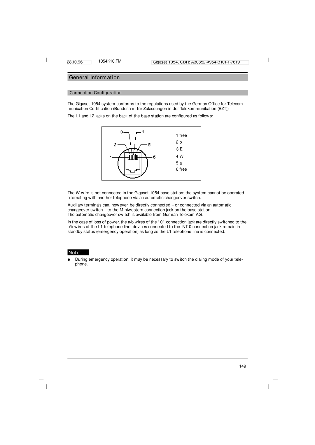
Connection Configuration
Glossary
TC System
Park Unpark a Call
Station
LED
Index
Hold 43, 95
Register Mobile unit
Quick Reference Operating Instructions Standard Mobile Unit
Dialing an Internal Telephone Number
Setting Tone Ring Pitch
Standard Mobile Unit in Operation Accepting a Call
Dialing an External Telephone Number
Accepting a Call Waiting Call
Internal Consultation during an External Call
External Consultation during an External Call
Forwarding an External Call to an Internal Station
Quick Reference Operating Instructions Comfort Mobile Unit
Setting the Handset Volume during a Call
Dialing an Internal Telephone Numberpage
Setting the Tone Ring Volume
Comfort Mobile Unit in Operation Accepting a Call
Dialing the Telephone Number from the Telephone Book
Storing the Telephone Number and Name in the Telephone Book
Quick Reference Operating Instructions Auxiliary Device
Toggle page 128 Telephone with Tone Dialing
Toggle page 128 Telephone with Pulse Dialing
Siemens Aktiengesellschaft