Hardware Information
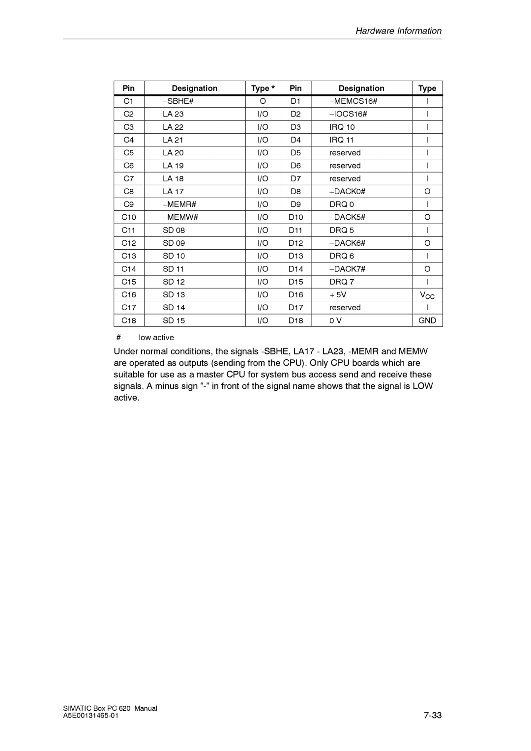
Pin | Designation | Type * | Pin | Designation | Type |
|
|
|
|
|
|
C1 |
| O | D1 |
| I |
|
|
|
|
|
|
C2 | LA 23 | I/O | D2 | I | |
|
|
|
|
|
|
C3 | LA 22 | I/O | D3 | IRQ 10 | I |
|
|
|
|
|
|
C4 | LA 21 | I/O | D4 | IRQ 11 | I |
|
|
|
|
|
|
C5 | LA 20 | I/O | D5 | reserved | I |
|
|
|
|
|
|
C6 | LA 19 | I/O | D6 | reserved | I |
|
|
|
|
|
|
C7 | LA 18 | I/O | D7 | reserved | I |
|
|
|
|
|
|
C8 | LA 17 | I/O | D8 |
| O |
|
|
|
|
|
|
C9 |
| I/O | D9 | DRQ 0 | I |
|
|
|
|
|
|
C10 |
| I/O | D10 |
| O |
|
|
|
|
|
|
C11 | SD 08 | I/O | D11 | DRQ 5 | I |
|
|
|
|
|
|
C12 | SD 09 | I/O | D12 |
| O |
|
|
|
|
|
|
C13 | SD 10 | I/O | D13 | DRQ 6 | I |
|
|
|
|
|
|
C14 | SD 11 | I/O | D14 |
| O |
|
|
|
|
|
|
C15 | SD 12 | I/O | D15 | DRQ 7 | I |
|
|
|
|
|
|
C16 | SD 13 | I/O | D16 | + 5V | VCC |
C17 | SD 14 | I/O | D17 | reserved | I |
|
|
|
|
|
|
C18 | SD 15 | I/O | D18 | 0 V | GND |
#low active
Under normal conditions, the signals
SIMATIC Box PC 620 Manual | |