Installation
2 Installation | 2.3 Mounting |
| 2 |
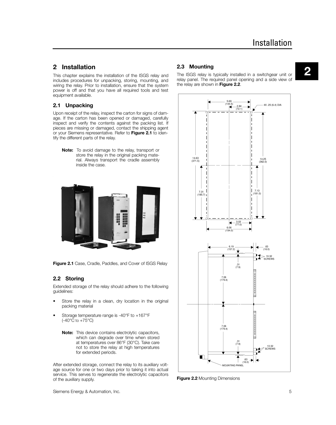
This chapter explains the installation of the ISGS relay and | The ISGS relay is typically installed in a switchgear unit or | ||
includes procedures for unpacking, storing, mounting, and | relay panel. The required panel opening and a side view of |
|
|
|
| ||
wiring the relay. Prior to installation, ensure that the system | the relay are shown in Figure 2.2. |
| |
power is off and that you have all required tools and test equipment available.
|
| 5.69 |
|
2.1 | Unpacking | (144.5) | 4X .25 (6.4) DIA |
2.84 | |||
|
| (72.1) |
|
Upon receipt of the relay, inspect the carton for signs of dam- |
|
| |
age. If the carton has been opened or damaged, carefully |
|
| |
inspect and verify the contents against the packing list. If |
|
| |
pieces are missing or damaged, contact the shipping agent |
|
| |
or your Siemens representative. Refer to Figure 2.1 to iden- |
|
| |
tify the different parts of the relay. |
|
| |
| Note: To avoid damage to the relay, transport or |
|
|
| store the relay in the original packing mate- | 14.63 |
|
| rial. Always transport the cradle assembly | 14.25 | |
| (371.5) | ||
| (362.0) | ||
. | inside the case. |
| |
|
| ||
|
| 7.31 | 7.13 |
|
| (181.0) | |
|
| (185.7) | |
|
|
| |
|
| 3.03 |
|
|
| (77.0) |
|
|
| 6.06 |
|
|
| (154.0) |
|
|
| 6.19 | .63 |
|
| (157.2) | (16.0) |
|
|
| |
|
|
| SCREWS |
Figure 2.1 Case, Cradle, Paddles, and Cover of ISGS Relay | .31 |
| |
|
| (7.9) |
|
2.2 | Storing | 7.06 |
|
(179.4) |
| ||
Extended storage of the relay should adhere to the following |
|
| |
guidelines: |
|
| |
• | Store the relay in a clean, dry location in the original |
|
|
| packing material |
|
|
• Storage temperature range is |
|
| |
|
|
| |
|
| 7.06 |
|
|
| (179.4) |
|
| Note: This device contains electrolytic capacitors, |
|
|
| which can degrade over time when stored | .31 |
|
| at temperatures over 86°F (30°C). Take care |
| |
| (7.9) | ||
| not to store the relay at high temperatures |
| |
|
| SCREWS | |
| for extended periods. |
|
|
|
| .63 |
|
After extended storage, connect the relay to its auxiliary volt- | (16.0) |
| |
MOUNTING PANEL |
| ||
age source for one or two days prior to taking it into actual |
|
| |
service. This serves to regenerate the electrolytic capacitors | Figure 2.2 Mounting Dimensions |
| |
of the auxiliary supply. |
| ||
|
| ||
Siemens Energy & Automation, Inc. | 5 |
