D
Appendix D: Acceptance Test Procedures
ISGS Acceptance Test | Directional Phase Time Overcurrent (67) Function |
|
|
Set the ISGS as follows: |
|
Parameter Set A | 7103 |
5000:5 Current Transformer (CT) | 1101 |
Curve SEA 5, Very Inverse | 1902 |
1 A Nominal Pickup | 1903 |
Time Dial per Chart | 1905 |
Impedance to 45° | 1907 |
Direction to Reverse | 1908 |
Trip Matrixed to Trip 1 Contact | 6401 |
Enable 67 | 1901 |
Disable Other Conflicting Functions | 1501, 1551, 1601, 1651, 1801, 1901, 2001, 2301 |
Raise 51 Pickup To Maximum | 1703 |
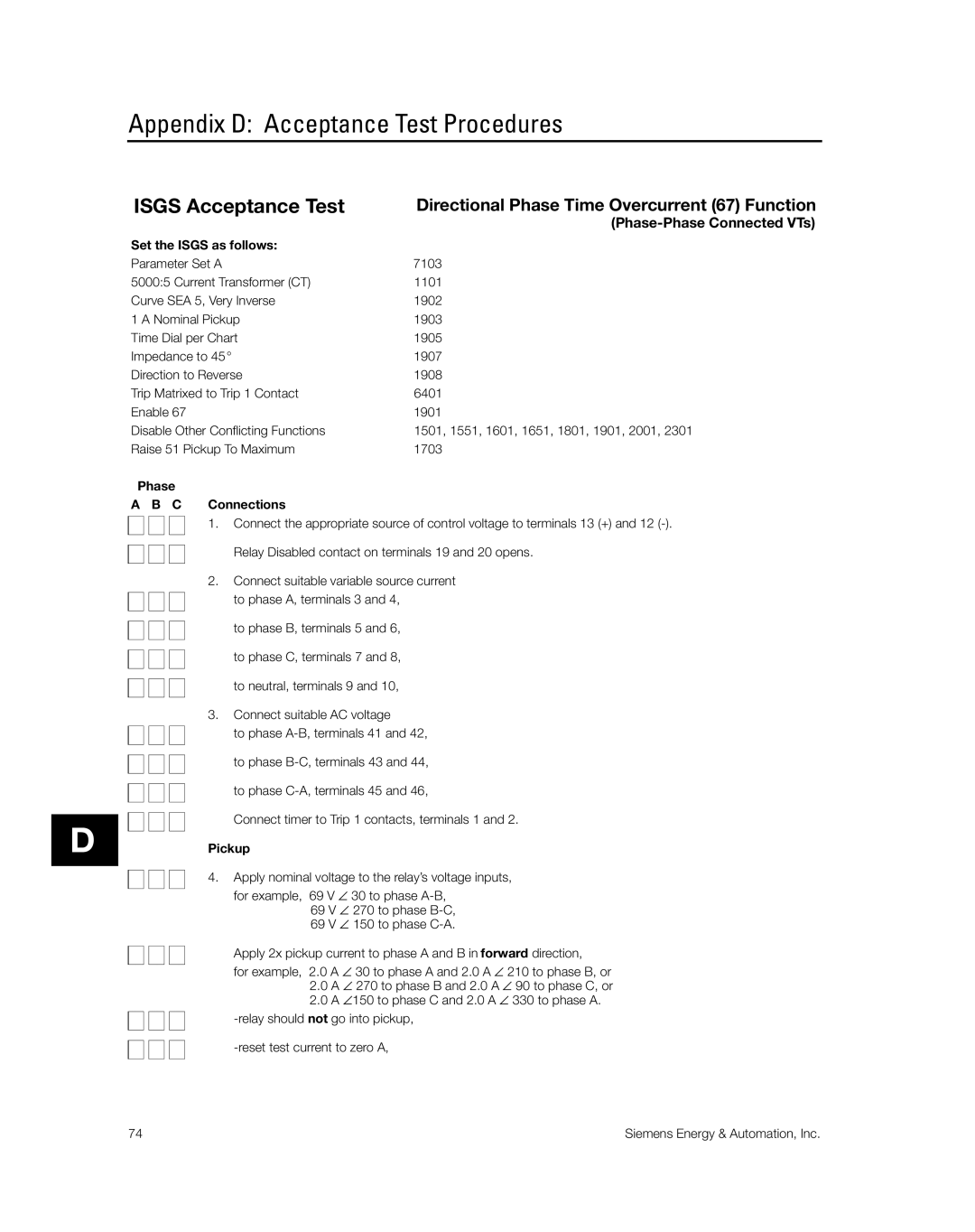
Phase
A B C Connections
1. Connect the appropriate source of control voltage to terminals 13 (+) and 12
Relay Disabled contact on terminals 19 and 20 opens.
2.Connect suitable variable source current
to phase A, terminals 3 and 4,
to phase B, terminals 5 and 6,
to phase C, terminals 7 and 8,
to neutral, terminals 9 and 10,
3.Connect suitable AC voltage
to phase
to phase
to phase
Connect timer to Trip 1 contacts, terminals 1 and 2.
Pickup
4. Apply nominal voltage to the relay’s voltage inputs,
for example, 69 V ∠ 30 to phase
Apply 2x pickup current to phase A and B in forward direction,
for example, 2.0 A ∠ 30 to phase A and 2.0 A ∠ 210 to phase B, or
2.0A ∠ 270 to phase B and 2.0 A ∠ 90 to phase C, or
2.0A ∠150 to phase C and 2.0 A ∠ 330 to phase A.
74 | Siemens Energy & Automation, Inc. |