Contents
Isgstm
Manual No. SG8158-00
Qualified Person
Contents
Page
Table of Contents
Settings Worksheet
Acceptance Test Procedures
Schematics
Service Request Form
Introduction
Safety
About this Manual
Standard Configuration
Product Description
Optional Configurations
Wisdom Software
Technical Specifications
Unpacking
Installation
Mounting
Storing
Wiring
Top
Isgs
Cradle Assembly
Communications
Keypad
Indicators
User Interface
LEDs
Password Protection
Menu
Standard Operating Procedures
A1500 Instantaneous Phase Overcurrent
A1502 Pickup 110A
User Interface
Switch Parameter Set
Siemens Energy & Automation, Inc
Hardware Configuration
Startup
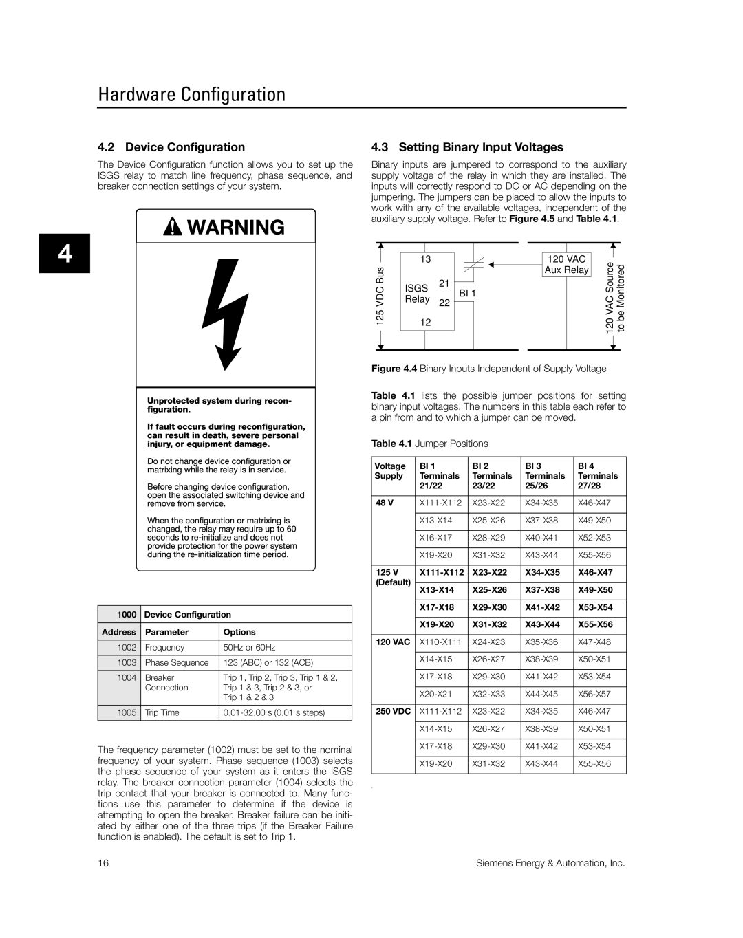
Device Configuration
Setting Binary Input Voltages
350
CT Configuration
VT Configuration
Isgs
52 = Power Circuit Breaker = Isgs Internal CT
Instantaneous Phase Overcurrent
Protective Function Configuration
Overview
Instantaneous Neutral or Ground Overcurrent 50N
High-Set Instantaneous Phase Overcurrent 50HS
High-Set Instantaneous Neutral or Ground Overcurrent 50HSN
Phase Time Overcurrent
Neutral Time Overcurrent 51N
Directional Phase Time Overcurrent
Blocking Capability for Breaker or Interrupter Saving
Directional Characteristic Siemens Energy & Automation, Inc
Directional Neutral or Ground Time Overcurrent 67N
Overvoltage
Undervoltage
Phase Sequence Voltage
Negative Sequence Voltage 47N
Underfrequency 81U
Overfrequency 81O
Breaker Failure 50BF
Demand Setpoints
Power Setpoints
Control & Communications
Matrixing Events to Outputs
Control & Communications
Binary Inputs
Binary Outputs
Comm Events
Trip Contacts
Breaker Monitoring
Logs and Breaker Monitor Reset
Breaker Operations Count
Hardware Status Relay Data
Self-Monitoring Value Supervision
Output Contact Status
Control & Communications
Active Set
Parameter Sets
Active Set
Default Set
Switching Sets
B1502 Pickup
Date and Time Setting
Passwords
Communications Port
Siemens Energy & Automation, Inc
Event Log
Data Acquisition
Trip Logs
Min/Max Logs
Current Minimum/Maximum Log
Voltage Minimum/Maximum Log
Power Minimum/Maximum Log
Frequency Minimum/Maximum Log
Current Values
Power Values
Metered Data
Voltage Values
Meter Display
Waveform Capture
Siemens Energy & Automation, Inc
Isgs Wisdom Software
Setup
Menus
Waveform Capture Siemens Energy & Automation, Inc
Demo Mode
Trip Log Data Display Siemens Energy & Automation, Inc
Siemens Energy & Automation, Inc
Instantaneous Curve
Appendix a Trip Curves & Equations
Standard Time Overcurrent Equation
Figure A.3 Short Inverse Curve SEA2
Definite Inverse Equation
Figure A.7 Extremely Inverse Curve SEA6
Custom Protective Curve
Squared-T Curve
Over/Undervoltage Curves
Figure A.11 Moderately Inverse Overvoltage Curve
Appendix B Metering
Accuracy
Power Conventions
Appendix C Menu Structure
Menu Structure
THD
Appendix C Menu Structure
Appendix D Acceptance Test Procedures
Acceptance Test Procedures
18.38
Neutral Time Overcurrent 51N Function
Appendix D Acceptance Test Procedures
Instantaneous Phase Overcurrent 50 Function
Undervoltage 27 Function
20.00 50.00 99.00 19.35 38.32 18.01
Overvoltage 59 Function
150
Directional Phase Time Overcurrent 67 Function
Phase-Neutral Connected VTs
18.38
Phase-Phase Connected VTs
Appendix D Acceptance Test Procedures
Directional Neutral Time Overcurrent 67N
Appendix D Acceptance Test Procedures
50/51 51N
Appendix E Schematics
IN1
Trip Systems
AC Capacitor
Isgs Settings Worksheet for Date
Set a
50HSN
Isgs Settings Worksheet for Date
Isgs Settings Worksheet for Date
Isgs Settings Worksheet for Date
Isgs Settings Worksheet for Date
Isgs Settings Worksheet for Date
Isgs Settings Worksheet for Date
Isgs Settings Worksheet for Date
Isgs Settings Worksheet for Date
Isgs Settings Worksheet for Date
BI1 BI2 BI3 BI4
6200 Binary Outputs 6202 001
6400 Trip Contacts 6401 001
VAR Varh
Isgs Settings Worksheet for Date
Isgs Settings Worksheet for Date
Isgs Settings Worksheet for Date Set B
Isgs Settings Worksheet for Date Set B
Isgs Settings Worksheet for Date Set B
Isgs Settings Worksheet for Date Set B
Isgs Settings Worksheet for Date Set B
Glossary
Glossary
Glossary
Glossary
Index
Index
Iii
Siemens Energy & Automation, Inc
Protective Relays Service Request Form
Protective Relay Group Customer Service Box Raleigh, NC
Siemens Energy & Automation, Inc Form SG6014-00
FAX Order Form
Page
Power Apparatus & Conditioning Division Box Raleigh, NC