User Interface
3.4 Menu
The ISGS relay menu (or memory map) is organized in a hier- archical structure that is made up of address blocks and addresses. The first level consists of address blocks. Each address block represents one complete function or two related functions and is identified by a unique
The second level consists of individual addresses confined to an address block. Each address represents a part of a func-
Block | Function | Address | Parameter |
|
|
|
|
A1500 | Instantaneous | 1501 | Function 50 |
| Phase Overcurrent | 1502 | Pickup 50 |
| (50) | 1504 | Delay 50 |
|
| 1510 | Freeze Wfm 1 50 |
|
| 1511 | Freeze Wfm 2 50 |
|
| 1512 | Block 50 |
| 1551 | Function 50HS | |
| neous Phase Over- | 1552 | Pickup 50HS |
| current (50HS) | 1560 | Freeze Wfm 1 HS |
|
| 1561 | Freeze Wfm 2 HS |
|
|
|
|
A1900 | Directional Phase | 1901 | Function |
| Time Overcurrent | 1902 | Curve |
| (67) | 1903 | Pickup |
|
| 1905 | Time Dial |
|
| 1906 | Filter |
|
| 1907 | Impedance |
|
| 1908 | Direction |
|
| 1910 | Freeze Wfm 1 |
|
| 1911 | Freeze Wfm 2 |
|
|
|
|
A2200 | Overvoltage (59) | ||
|
|
|
|
Figure 3.1 Example of Menu Structure Displaying Address Blocks with Two Related Functions, an Individual Function, and an Unavailable Function.
A complete ISGS relay menu with parameter listing is pro- vided in Appendix C. The various parameter settings are shown in the respective section describing the complete function.
Only certain protective function parameters have two set- tings. All A settings are grouped under parameter set A, and all B settings are grouped under parameter set B. Each parameter set automatically includes all the regular parame- ters that can be programmed to only one setting at a time and, therefore, apply to both sets. Examples are protective function enable settings and matrixed output contacts such as waveform buffers and blocking. For more information on parameter sets, refer to Section 6.11.
The LCD identifies functions that include parameters config- urable for A and B settings by preceding the function’s address block number with the letter A or the letter B, depending on which parameter set is currently displayed. Refer to Figure 3.2.
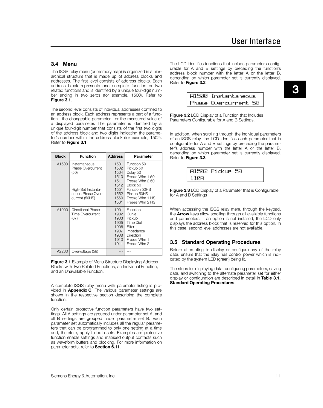
A1500 Instantaneous
Phase Overcurrent 50
Figure 3.2 LCD Display of a Function that Includes Parameters Configurable for A and B Settings.
In addition, when scrolling through the individual parameters of an ISGS relay, the LCD identifies each parameter that is configurable for A and B settings by preceding the parame- ter’s address number with the letter A or the letter B, depending on which parameter set is currently displayed. Refer to Figure 3.3
A1502 Pickup 50
110A
Figure 3.3 LCD Display of a Parameter that is Configurable for A and B Settings
When accessing the ISGS relay menu through the keypad, the Arrow keys allow scrolling through all available functions and parameters. If an option is not installed, the LCD only displays the address block that is reserved for this option. In this case, second level addresses are not available.
3.5 Standard Operating Procedures
Before attempting to display or configure any of the relay data, ensure that the relay has control power which is indi- cated by the system LED (green) being lit.
The steps for displaying data, configuring parameters, saving data, and switching to the alternate parameter set for either display or configuration are described in detail in Table 3.1, Standard Operating Procedures.
3
Siemens Energy & Automation, Inc. | 11 |