Control & Communications
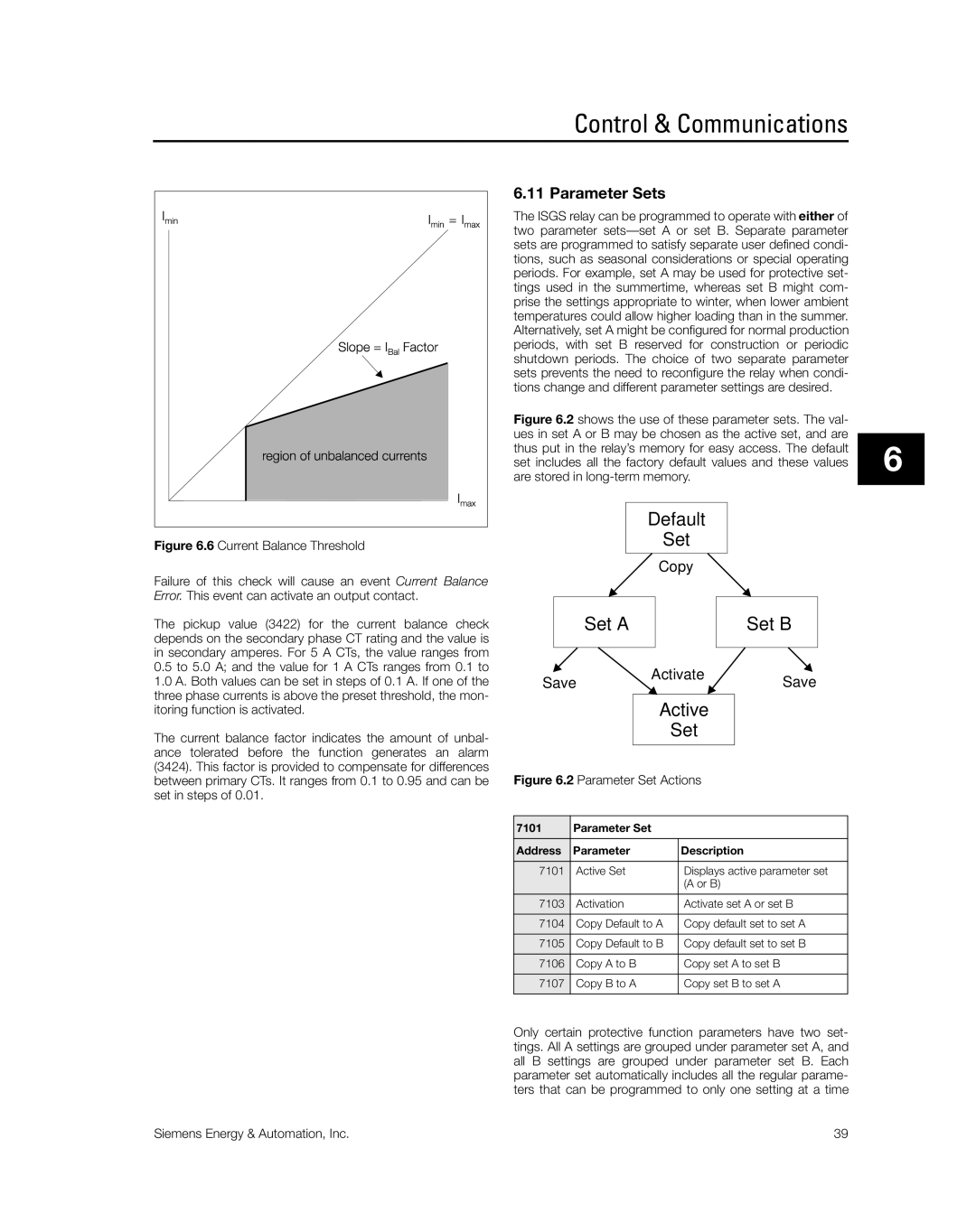
Figure 6.6 Current Balance Threshold
Failure of this check will cause an event Current Balance Error. This event can activate an output contact.
The pickup value (3422) for the current balance check depends on the secondary phase CT rating and the value is in secondary amperes. For 5 A CTs, the value ranges from
0.5to 5.0 A; and the value for 1 A CTs ranges from 0.1 to
1.0A. Both values can be set in steps of 0.1 A. If one of the three phase currents is above the preset threshold, the mon- itoring function is activated.
The current balance factor indicates the amount of unbal- ance tolerated before the function generates an alarm (3424). This factor is provided to compensate for differences between primary CTs. It ranges from 0.1 to 0.95 and can be set in steps of 0.01.
6.11 Parameter Sets
The ISGS relay can be programmed to operate with either of two parameter
Figure 6.2 shows the use of these parameter sets. The val- ues in set A or B may be chosen as the active set, and are thus put in the relay’s memory for easy access. The default set includes all the factory default values and these values are stored in long-term memory.
|
|
| Default |
|
| |
|
|
|
| Set |
|
|
|
|
|
|
|
|
|
|
|
|
| Copy |
|
|
|
|
|
|
|
|
|
| Set A |
|
|
| Set B | |
|
|
|
|
|
|
|
Save | Activate |
| Save | |||
|
|
| ||||
Active
Set
Figure 6.2 Parameter Set Actions
7101 | Parameter Set |
|
Address | Parameter | Description |
7101 | Active Set | Displays active parameter set |
|
| (A or B) |
7103 | Activation | Activate set A or set B |
7104 | Copy Default to A | Copy default set to set A |
7105 | Copy Default to B | Copy default set to set B |
7106 | Copy A to B | Copy set A to set B |
7107 | Copy B to A | Copy set B to set A |
|
|
|
6
Only certain protective function parameters have two set- tings. All A settings are grouped under parameter set A, and all B settings are grouped under parameter set B. Each parameter set automatically includes all the regular parame- ters that can be programmed to only one setting at a time
Siemens Energy & Automation, Inc. | 39 |