Data Acquisition
7.5 Meter Display
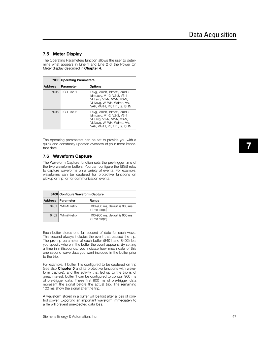
The Operating Parameters function allows the user to deter- mine what appears in Line 1 and Line 2 of the Power On Meter display described in Chapter 4.
7000 | Operating Parameters | |
Address | Parameter | Options |
7005 | LCD Line 1 | I avg, Idmd1, Idmd2, Idmd3, |
|
| Idmdavg, |
|
| VLLavg, |
|
| VLNavg, W, WH, Wdmd, VA, |
|
| VAR, VARH, PF, f, I1, I2, I3, IN |
7006 | LCD Line 2 | I avg, Idmd1, Idmd2, Idmd3, |
|
| Idmdavg, |
|
| VLLavg, |
|
| VLNavg, W, WH, Wdmd, VA, |
|
| VAR, VARH, PF, f, I1, I2, I3, IN |
|
|
|
The operating parameters can be set to provide you with a quick and constantly updated overview of your most impor- tant data.
7.6 Waveform Capture
The Waveform Capture function sets the
8400 | Configure Waveform Capture | |
Address | Parameter | Range |
8401 | Wfm1Pretrp | |
|
| (1 ms steps) |
8402 | Wfm2Pretrp | |
|
| (1 ms steps) |
|
|
|
Each buffer stores one full second of data for each wave. This second always includes the event that caused the trip. The
For example, if buffer 1 is configured to be captured on trip (see also Chapter 5 and its protective functions with wave- form capture), and the activity that led up to the trip is of great interest, buffer 1 can be configured to contain 900 ms of
A waveform stored in a buffer will be lost after a loss of con- trol power. Exporting an important waveform immediately to a file will prevent unexpected data loss.
7
Siemens Energy & Automation, Inc. | 47 |
