connection | system. |
typical | ACtrip |
AC1 | 1 | 2 |
|
|
|
|
|
|
|
|
|
|
|
|
|
|
|
|
1 |
| RES | RES |
|
|
|
|
|
|
|
|
|
|
|
|
|
| |
|
|
|
|
|
| 1 | Trip |
|
| 13 |
|
|
|
|
|
| ||
|
|
| 1 |
|
|
|
|
| Optional | 48 |
| |||||||
|
|
| CS |
|
| Common |
|
| PS |
| + | |||||||
|
|
| R | G |
|
|
|
|
| IN1 |
|
|
| |||||
|
|
|
|
|
|
|
|
|
|
|
|
| ||||||
2 |
|
| 2 | T |
|
|
|
|
|
|
| Communications |
| - | ||||
|
|
|
|
|
|
| Trip Source |
| Power | (see below) | 49 | |||||||
|
|
|
|
|
|
| Trip 1 | Trip 2 |
|
|
|
|
|
| ||||
|
|
|
|
|
|
|
|
|
|
| Case |
|
| |||||
| 3 |
|
|
|
|
|
|
|
| Impedance |
| Supply |
|
| Ground |
|
| |
| CS |
|
|
|
|
|
|
| Sense Circuit* |
|
|
|
| |||||
| 95C |
|
|
|
|
|
|
|
|
|
| 19 |
| |||||
|
|
|
|
|
|
|
|
|
|
|
|
|
|
|
| |||
| C |
|
|
|
|
|
|
|
|
|
|
|
|
|
|
| ||
|
|
|
|
|
|
|
|
|
|
|
|
|
| Relay |
| |||
| 4 |
|
|
|
|
|
|
|
|
|
|
|
|
|
| |||
|
|
|
|
|
|
|
|
|
|
| PS | BI | BI |
|
| |||
|
|
|
|
|
|
|
|
|
|
| Disabled* |
|
| |||||
|
|
|
|
|
|
|
|
|
|
|
|
|
| |||||
AC Supply |
|
|
|
|
|
|
|
|
|
|
| IN2 | Trip BSW |
|
| 20 |
| |
|
|
|
|
|
| 2 | 11 | 17 | 16 | 18 | 12 | 15 | 14 |
|
|
| ||
(120 VAC |
|
|
|
|
|
|
|
|
|
|
|
|
|
|
| ISGS Relay |
| |
Only) |
|
|
|
|
|
|
|
|
|
|
|
|
|
|
|
| ||
|
|
|
|
|
|
|
|
|
|
|
|
|
|
|
|
|
| |
3 | 13 |
| 16 | 4 | 11 |
| 1 |
|
|
|
|
|
|
| *Contact is closed when | |||
52 |
|
|
|
|
|
| 52a |
|
|
|
|
|
|
| relay is out of service |
| ||
| 52 |
|
|
|
|
| 95C |
|
|
|
|
|
|
|
|
| ||
|
|
|
|
|
|
|
|
|
|
|
|
|
|
|
| |||
| LS | 88 |
| CTD |
|
|
|
|
|
|
|
|
|
|
| |||
| SRC |
| 52T |
| Optional |
|
|
|
| RES |
| RES |
|
| ||||
|
|
|
|
|
|
|
|
|
|
| ||||||||
|
|
|
|
|
|
|
|
|
|
|
|
|
|
|
| |||
|
|
|
|
|
|
| 52a |
| Remote |
|
|
|
|
|
|
| ||
|
|
|
|
|
|
|
|
|
|
|
|
|
|
|
|
| ||
|
|
|
|
|
|
| Breaker |
| Closing |
|
|
|
|
|
|
|
|
|
4 | 15 |
|
| 14 | 2 |
|
|
|
|
|
|
|
|
|
|
|
| |
|
|
|
|
|
|
|
|
|
|
|
|
|
|
| ||||
|
|
|
|
|
|
|
|
|
|
|
|
| 52a | 52b |
|
| ||
|
|
|
|
|
|
|
|
|
|
|
|
|
|
|
| |||
Slug |
|
|
|
|
|
|
|
|
|
|
|
|
|
|
|
|
| |
3 | 3 |
| 4 |
|
|
|
|
|
|
|
|
|
|
|
|
|
|
|
|
|
|
|
|
|
|
|
|
|
|
|
|
|
|
|
| ||
Siemens Energy & Automation, Inc.
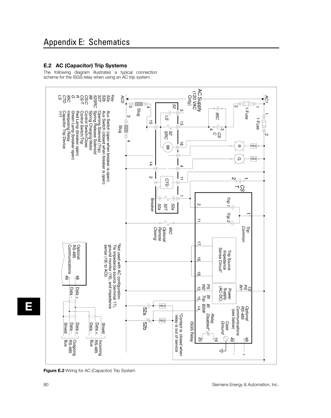
Appendix E: Schematics
Trip Systems | illustrates a | when using an |
E.2 AC (Capacitor) | The following diagram | scheme for the ISGS relay |
AC0Slug
Key
52a Aux Switch (open when breaker is open)
52b Aux Switch (closed when breaker is open)
52T Opening Solenoid (Trip) 52SRC Spring Release Solenoid
88Spring Charging Motor CS/C Control Switch/Close CS/T Control Switch/Trip
R Red Lamp (breaker open)
G Green Lamp (breaker open)
95C Interposing Relay
CTD Capacitor Trip Device
LS ???
*Not used with AC configuration.
Tie impedance source (terminal 17), ground monitor (16), and impedance
sense (18) to AC0.
Shield
Incoming
Data +
Optional | 48 | Data + | Data + | Outgoing |
| Data - | Data - | ||
Communications |
| |||
49 |
|
| ||
|
| Shield Bus | ||
E