D
Appendix D: Acceptance Test Procedures
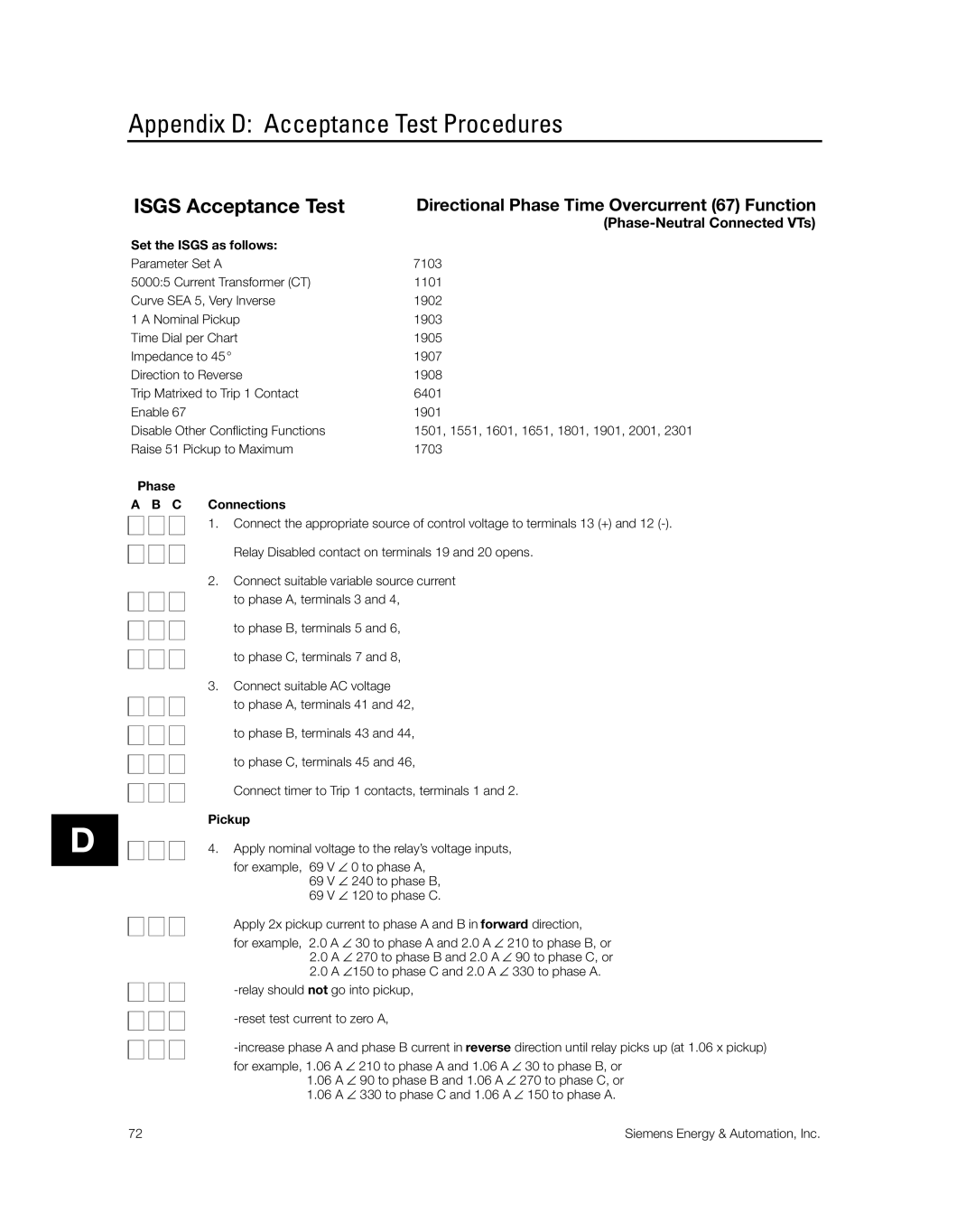
ISGS Acceptance Test | Directional Phase Time Overcurrent (67) Function |
|
|
Set the ISGS as follows: |
|
Parameter Set A | 7103 |
5000:5 Current Transformer (CT) | 1101 |
Curve SEA 5, Very Inverse | 1902 |
1 A Nominal Pickup | 1903 |
Time Dial per Chart | 1905 |
Impedance to 45° | 1907 |
Direction to Reverse | 1908 |
Trip Matrixed to Trip 1 Contact | 6401 |
Enable 67 | 1901 |
Disable Other Conflicting Functions | 1501, 1551, 1601, 1651, 1801, 1901, 2001, 2301 |
Raise 51 Pickup to Maximum | 1703 |
Phase
A B C Connections
1. Connect the appropriate source of control voltage to terminals 13 (+) and 12
Relay Disabled contact on terminals 19 and 20 opens.
2.Connect suitable variable source current
to phase A, terminals 3 and 4,
to phase B, terminals 5 and 6,
to phase C, terminals 7 and 8,
3.Connect suitable AC voltage
to phase A, terminals 41 and 42,
to phase B, terminals 43 and 44,
to phase C, terminals 45 and 46,
Connect timer to Trip 1 contacts, terminals 1 and 2.
Pickup
4. Apply nominal voltage to the relay’s voltage inputs,
for example, 69 | V ∠ 0 to phase A, |
69 | V ∠ 240 to phase B, |
69 | V ∠ 120 to phase C. |
Apply 2x pickup current to phase A and B in forward direction,
for example, 2.0 A ∠ 30 to phase A and 2.0 A ∠ 210 to phase B, or
2.0A ∠ 270 to phase B and 2.0 A ∠ 90 to phase C, or
2.0A ∠150 to phase C and 2.0 A ∠ 330 to phase A.
1.06A ∠ 90 to phase B and 1.06 A ∠ 270 to phase C, or
1.06A ∠ 330 to phase C and 1.06 A ∠ 150 to phase A.
72 | Siemens Energy & Automation, Inc. |