Control & Communications
The Trip Source Impedance parameter (8301) can be enabled or disabled. When enabled, the circuit periodically monitors the trip supply voltage (auxiliary voltage, station bat- tery) and will perform an action (for example, close a binary output) should the voltage drop below ANSI minimum val- ues. Monitoring the trip source (auxiliary power) to detect bad connections and weak batteries is done by periodically drawing a small current from the trip supply and monitoring the subsequent sag in the voltage. Using averaging tech- niques, the trip source impedance can be estimated. Based on this estimate, an error message is given if the source volt- age drops below ANSI minimum values during a trip event. When the function is enabled, it can cause the actuation of any of the output contacts. This circuit can function only in true DC trip systems. It should be disabled and the inputs left disconnected when the device is used in AC trip systems.
The Trip Source Fail parameter of the Trip Source Impedance function (8302), when set to yes, allows the relay fail contact to be asserted when the monitoring function detects an error. When set to no, the relay fail contact is not affected.
The Trip Coil Continuity function (8303), when enabled, senses a trip coil continuity error, causes an action to be taken, and logs the event if the 52a and 52b switches are ever both open at the same time for more than 100 ms. No other time delay is implemented. When the function detects the error, the function is considered to be in pickup until the condition is no longer present.
The Trip Coil Fail parameter of the Trip Coil Continuity func- tion (8304), when set to yes, allows the relay fail contact to be asserted when the monitoring function detects an error. When set to no, the relay fail contact is not affected.
Because the 52b switch does not need to interrupt the cur- rent through the trip coil, it provides a reliable indication of breaker position: when it is open, the breaker is considered closed. The practice (in DC trip systems) of placing a red sta- tus indicator lamp in series with the trip coil allows a conve- nient method for monitoring the continuity of the trip coil. When the circuit breaker is closed, the 52a switch is closed and the voltage across them and the trip coil is small because most of the voltage drop occurs across the indicat- ing lamp circuit. If the trip coil is open or the
The Breaker Mechanism function (8305), when enabled, senses an error in the mechanism that controls the position of one or both switches (breaker mechanism error), causes an action to be taken, and an event to be logged if the switches are ever both closed for more than 100 ms. No other time delay is implemented. When this function detects an error, it is considered to be in pickup until the condition is no longer present.
The ISGS relay considers the
6.7 Logs and Breaker Monitor Reset
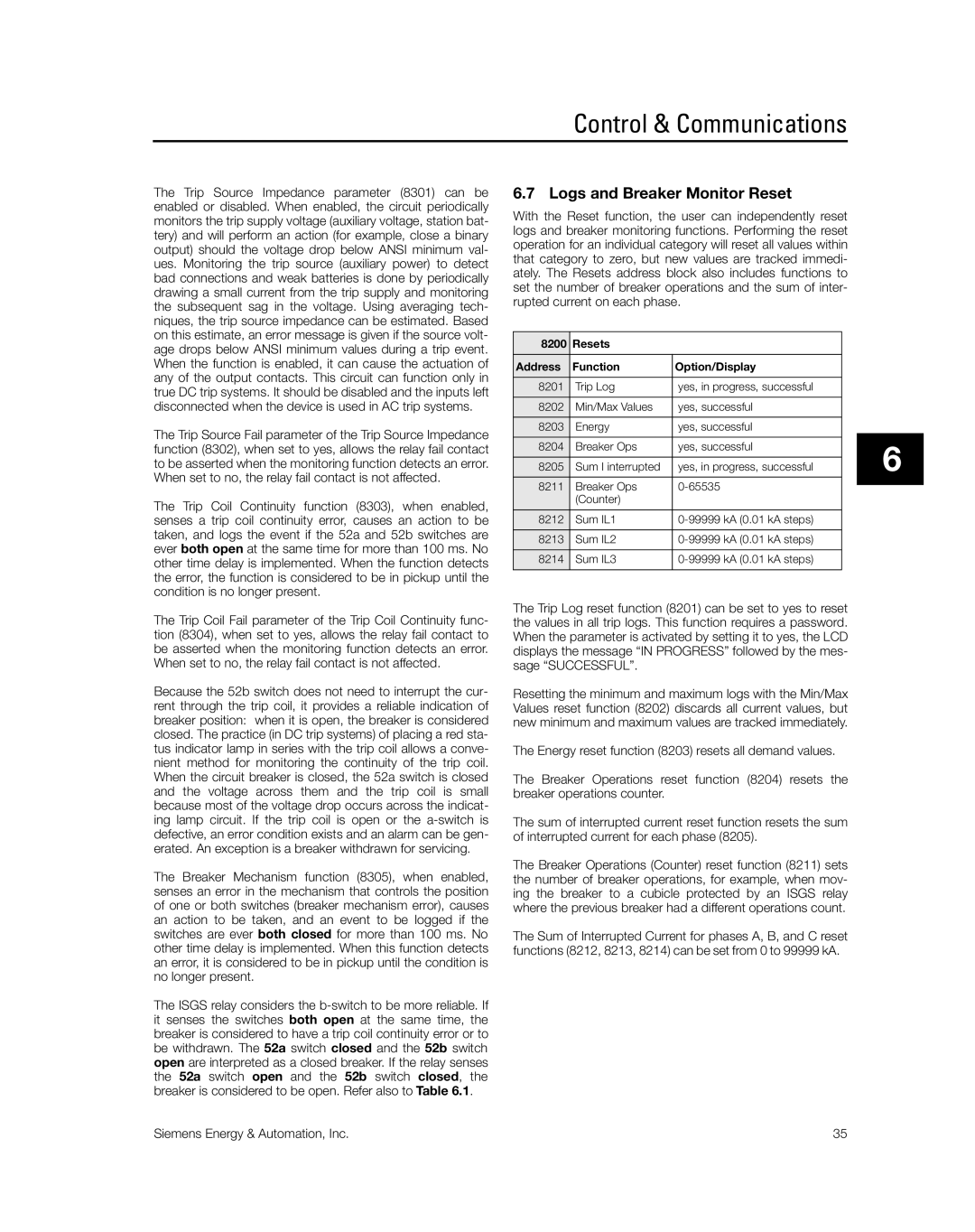
With the Reset function, the user can independently reset logs and breaker monitoring functions. Performing the reset operation for an individual category will reset all values within that category to zero, but new values are tracked immedi- ately. The Resets address block also includes functions to set the number of breaker operations and the sum of inter- rupted current on each phase.
8200 | Resets |
|
Address | Function | Option/Display |
8201 | Trip Log | yes, in progress, successful |
8202 | Min/Max Values | yes, successful |
8203 | Energy | yes, successful |
8204 | Breaker Ops | yes, successful |
8205 | Sum I interrupted | yes, in progress, successful |
8211 | Breaker Ops | |
| (Counter) |
|
8212 | Sum IL1 | |
8213 | Sum IL2 | |
8214 | Sum IL3 | |
|
|
|
The Trip Log reset function (8201) can be set to yes to reset the values in all trip logs. This function requires a password. When the parameter is activated by setting it to yes, the LCD displays the message “IN PROGRESS” followed by the mes- sage “SUCCESSFUL”.
Resetting the minimum and maximum logs with the Min/Max Values reset function (8202) discards all current values, but new minimum and maximum values are tracked immediately.
The Energy reset function (8203) resets all demand values.
The Breaker Operations reset function (8204) resets the breaker operations counter.
The sum of interrupted current reset function resets the sum of interrupted current for each phase (8205).
The Breaker Operations (Counter) reset function (8211) sets the number of breaker operations, for example, when mov- ing the breaker to a cubicle protected by an ISGS relay where the previous breaker had a different operations count.
The Sum of Interrupted Current for phases A, B, and C reset functions (8212, 8213, 8214) can be set from 0 to 99999 kA.
6
Siemens Energy & Automation, Inc. | 35 |