| Appendix D: Acceptance Test Procedures |
|
|
ISGS Acceptance Test | Instantaneous Phase Overcurrent (50) Function |
Set the ISGS as follows: |
|
Parameter Set A | 7103 |
5000:5 Current Transformer (CT) | 1102 |
Curve SEA 5, Very Inverse | 1702 |
20 A Nominal Pickup | 1703 |
Time Dial 9.9 | 1705 |
Instantaneous Pickup 1 A | 1501, 1502, 1503 |
Instantaneous Time Delay 0.0 | 1504 |
Trip Matrixed to Trip 1 Contact | 6401 |
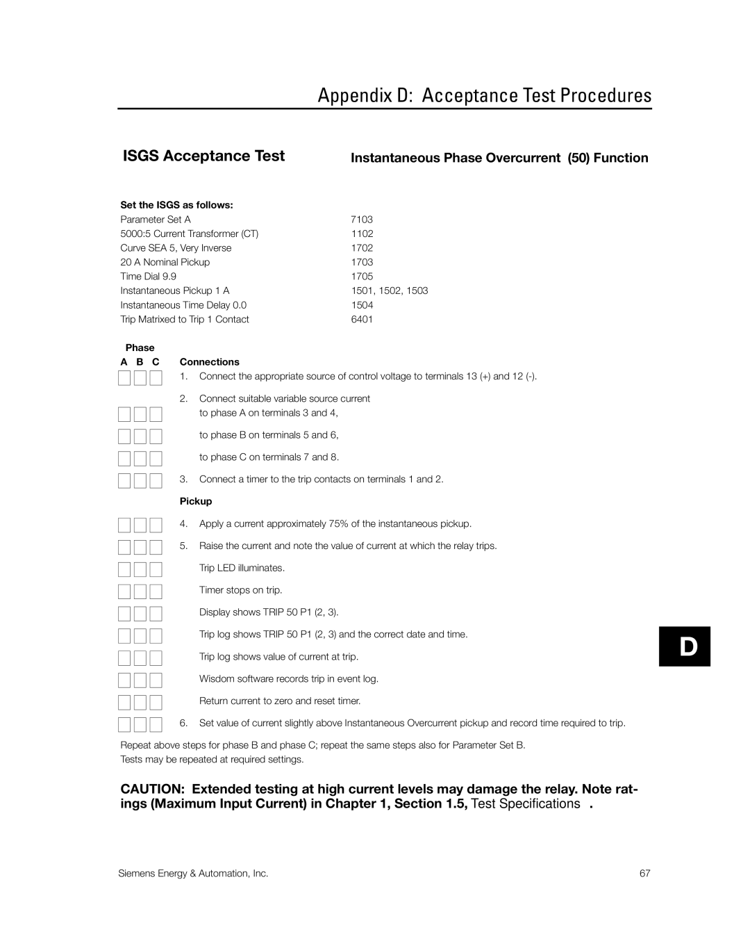
Phase
A B C Connections
1. Connect the appropriate source of control voltage to terminals 13 (+) and 12
2.Connect suitable variable source current
to phase A on terminals 3 and 4,
to phase B on terminals 5 and 6,
to phase C on terminals 7 and 8.
3. Connect a timer to the trip contacts on terminals 1 and 2.
Pickup
4. Apply a current approximately 75% of the instantaneous pickup.
5. Raise the current and note the value of current at which the relay trips.
Trip LED illuminates.
Timer stops on trip.
Display shows TRIP 50 P1 (2, 3).
Trip log shows TRIP 50 P1 (2, 3) and the correct date and time.
Trip log shows value of current at trip.
Wisdom software records trip in event log.
Return current to zero and reset timer.
6. Set value of current slightly above Instantaneous Overcurrent pickup and record time required to trip.
Repeat above steps for phase B and phase C; repeat the same steps also for Parameter Set B. Tests may be repeated at required settings.
CAUTION: Extended testing at high current levels may damage the relay. Note rat- ings (Maximum Input Current) in Chapter 1, Section 1.5, Test Specifications.
D
Siemens Energy & Automation, Inc. | 67 |