Hardware Configuration
4.4 CT Configuration
The CT Configuration function allows you to set up the ISGS relay to match the phase CT primary rating, the neutral or ground CT primary rating, and the CT input’s normal power flow setting of your system. For CT connections refer to Figure 4.8.
4
Main Bus | |
ISGS |
|
| ISGS |
Power | Power |
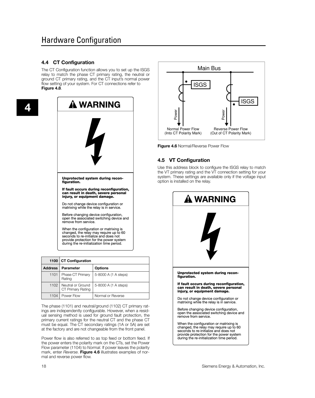
Normal Power Flow | Reverse Power Flow |
(Into CT Polarity Mark) | (Out of CT Polarity Mark) |
Figure 4.6 Normal/Reverse Power Flow
4.5 VT Configuration
Use this address block to configure the ISGS relay to match the VT primary rating and the VT connection setting for your system. These settings are available only if the voltage input option is installed on the relay.
1100 | CT Configuration |
|
Address | Parameter | Options |
1101 | Phase CT Primary | |
| Rating |
|
1102 | Neutral or Ground | |
| CT Primary Rating |
|
1104 | Power Flow | Normal or Reverse |
|
|
|
The phase (1101) and neutral/ground (1102) CT primary rat- ings are independently configurable. However, when a resid- ual sensing method is used for ground fault protection, the primary current ratings for the neutral CT and the phase CT must be equal. The CT secondary ratings (1A or 5A) are set at the factory and are not changeable from the front panel.
Power flow is also referred to as top feed or bottom feed. If the power enters the polarity mark on the CTs, set the Power Flow parameter (1104) to Normal. If power leaves the polarity mark, enter Reverse. Figure 4.6 illustrates examples of nor- mal and reverse power flow.
18 | Siemens Energy & Automation, Inc. |