1
Introduction
Signal Words
The signal words Danger, Warning, and Caution used in this manual indicate the degree of hazard that the user or operator can encounter. These words are defined as follows:
•Danger - indicates an imminently hazardous situation which, if not avoided, will result in death or serious injury
•Warning - indicates a potentially hazardous situation which, if not avoided, could result in death or serious injury
•Caution - indicates a potentially hazardous situation which, if not avoided, could result in moderate or minor injury
Required Procedures
In addition to normal safety practices, user personnel must adhere to the following procedures:
1.Always work on
2.Always perform maintenance on equipment employing springs after the
3.Always let an interlock device or safety mechanism per- form its function without forcing or defeating the device.
Field Service Operation
Siemens can provide competent,
1.3 Product Description
The ISGS relay is a general purpose, multifunction, micropro-
The ISGS relay provides two breaker tripping contacts and one relay disabled (alarm) contact. The relay disabled contact is a normally closed contact which opens when the relay is functioning properly.
1.3.1Standard Configuration
The ISGS relay base unit includes the following standard pro- tection, metering, and monitoring features:
•Instantaneous Phase Overcurrent (50) protection
•Instantaneous Neutral or Ground Overcurrent (50N) protection
•Phase Time Overcurrent (51) protection
•Neutral or Ground Time Overcurrent (51N) protection
|
|
|
|
|
| ISGS |
|
|
|
|
|
| System |
|
|
|
|
|
| Pickup |
|
|
|
|
|
| Trip |
| Pass | Direct | 7 | 8 | 9 | |
| word | Addr | ||||
Target | Target | Trip | 4 | 5 | 6 | |
Reset | Reset | Log | ||||
|
|
|
| 1 | 2 | 3 |
|
|
|
|
| 0 | |
|
|
| F | Pass | ∞ Enter | |
|
|
| word | |||
|
|
|
| Yes | No |
|
|
|
|
|
| Data Port | |
|
| ISGS | LR |
|
|
|
| Cat# |
|
|
| ||
| VPSn 120VAC/250VDC |
|
|
| ||
| IPH | 5A | IC 5A |
|
|
|
| Ser# | Beta05HW15W2.XX |
|
|
| |
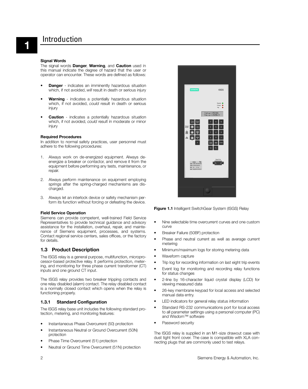
Figure 1.1 Intelligent SwitchGear System (ISGS) Relay
•Nine selectable time overcurrent curves and one custom curve
•Breaker Failure (50BF) protection
•Phase and neutral current as well as average current metering
•Minimum/maximum logs for storing metering data
•Waveform capture
•Trip log for recording information on last eight trip events
•Event log for monitoring and recording relay functions for status changes
•2-line by 16-character liquid crystal display (LCD) for viewing measured data
•26-key membrane keypad for local access and selected manual data entry.
•LED indicators for general relay status information
•Standard RS-232 communications port for local access to all parameter settings using a personal computer (PC) and Wisdom™ software
•Password security
The ISGS relay is supplied in an M1-size drawout case with dust tight front cover. The case is compatible with XLA con- necting plugs that are commonly used to test relays.
2 | Siemens Energy & Automation, Inc. |