|
|
|
|
| . |
| User Interface | ||
|
|
|
|
|
|
| |||
|
|
|
|
|
|
| |||
3 | User Interface |
|
|
|
| ||||
Key | Name | Function | |||||||
|
|
|
|
| |||||
Operation, parameter selection, and control of the ISGS relay |
|
|
|
| |||||
| Password | Accesses the password function, | |||||||
are performed using the front panel controls and indicators. |
| ||||||||
|
| which is required for programming | |||||||
They consist of a |
| l | relay settings. | ||||||
|
|
|
| ||||||
| Direct Addr | Allows direct entry of addresses. | |||||||
diodes (LEDs), and the front port. |
| ||||||||
|
| ||||||||
3.1 | Keypad |
|
|
|
|
|
| ||
The relay can be controlled via the keypad, the front port, or |
|
|
|
| |||||
| Trip Log | Displays the trip log. | |||||||
the optional rear port. This manual covers only keypad oper- |
|
|
|
| |||||
ations. For information about communicating with the ISGS |
|
|
|
| |||||
relay via the data ports, refer to the documentation supplied |
|
|
|
| |||||
with the communications software (WinPM or Wisdom). |
| Target Reset | Resets the Trip LED. | ||||||
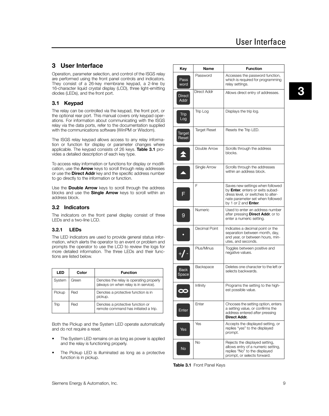
The ISGS relay keypad allows access to any relay informa- |
|
|
|
| |||||
tion or function for display or parameter changes where |
|
|
|
| |||||
| Double Arrow | Scrolls through the address | |||||||
applicable. The keypad consists of 26 keys. Table 3.1 pro- |
| ||||||||
vides a detailed description of each key type. |
|
| blocks. | ||||||
|
|
|
| ||||||
To access relay information or functions for display or modifi- |
|
|
|
| |||||
| Single Arrow | Scrolls through the addresses | |||||||
cation, use the Arrow keys to scroll through relay addresses |
| ||||||||
|
| within an address block. | |||||||
or use the Direct Addr key and the specific address number |
|
| |||||||
|
|
|
| ||||||
to go directly to the information or function. |
|
|
|
| |||||
|
|
|
|
|
|
|
|
| |
Use the Double Arrow keys to scroll through the address |
| F | Saves new settings when followed | ||||||
|
| by Enter, enters or exits subad- | |||||||
blocks and use the Single Arrow keys to scroll within an |
|
| |||||||
|
| dress level, or switches to alter- | |||||||
address block. |
|
|
|
| |||||
|
|
|
| nate parameter set when followed | |||||
|
|
|
|
|
|
| |||
|
|
|
|
|
|
| by 1 or 2 and Enter. | ||
3.2 | Indicators |
|
|
|
|
|
| ||
|
|
| Numeric | Used to enter an address number | |||||
|
|
|
|
|
| ||||
The | indicators on the | front panel display consist of three |
|
| after pressing Direct Addr, or to | ||||
LEDs and a |
|
| enter a numeric setting. | ||||||
|
|
|
| ||||||
|
|
|
|
|
|
|
| ||
3.2.1 | LEDs |
|
|
| Decimal Point | Indicates a decimal point or the | |||
|
|
|
|
|
|
| separation between month, day, | ||
The LED indicators are used to provide general status infor- |
|
| and year, or between hours, min- | ||||||
mation, which alerts the operator to an event or problem and |
|
| utes, and seconds. | ||||||
prompts the operator to use the LCD to review the logs for |
|
|
|
| |||||
| Plus/Minus | Toggles between positive and | |||||||
more detailed information. The three LEDs and their func- |
| ||||||||
|
| negative values. | |||||||
tions are listed below. |
|
|
|
|
|
| |||
|
|
|
|
|
|
|
|
| |
|
|
|
|
|
| Backspace | Deletes one character to the left or | ||
LED | Color | Function |
|
|
| selects backwards. | |||
|
|
|
|
| |||||
|
|
|
|
|
|
|
| ||
System | Green | Denotes the relay is operating properly |
|
|
|
|
| ||
|
|
| (always on when relay is in service). |
|
| Infinity | Programs the setting to the high- | ||
|
|
|
|
|
|
| est possible value. | ||
Pickup | Red | Denotes a protective function is in |
|
|
| ||||
|
|
|
|
| |||||
|
|
| pickup. |
|
|
|
|
| |
|
|
|
|
|
|
|
|
| |
Trip |
| Red | Denotes a protective function or |
|
| Enter | Chooses the setting option, enters | ||
|
|
| remote command has initiated a trip. |
|
|
| a setting value, or confirms the | ||
|
|
|
|
|
|
| address entered after pressing | ||
|
|
|
|
|
|
| |||
|
|
|
|
|
|
| Direct Addr. | ||
|
|
|
|
| |||||
Both the Pickup and the System LED operate automatically |
| Yes | Accepts the displayed setting, or | ||||||
and do not require a reset. |
|
| replies “yes” to the displayed | ||||||
|
|
|
|
|
|
| prompt. | ||
•The System LED remains on as long as power is applied
| and the relay is functioning properly. | No | Rejects the displayed setting, |
|
|
| allows entry of a numeric setting, |
• | The Pickup LED is illuminated as long as a protective |
| replies “No” to the displayed |
| prompt, or selects forward. | ||
| function is in pickup. |
| |
|
|
|
Table 3.1 Front Panel Keys
3
Siemens Energy & Automation, Inc. | 9 |