Installation
2
Mount the relay using the following steps.
1.Install the relay
2.Connect the case ground to the terminal lug on the back of the
3.Wire as described in Section 2.4.
Use toothed washers to ensure solid metal contact through paint of cover and panel
Case ground, #12 or braided cable to good cubicle ground, as short as possible
Figure 2.3 Case Grounding
2.4 Wiring
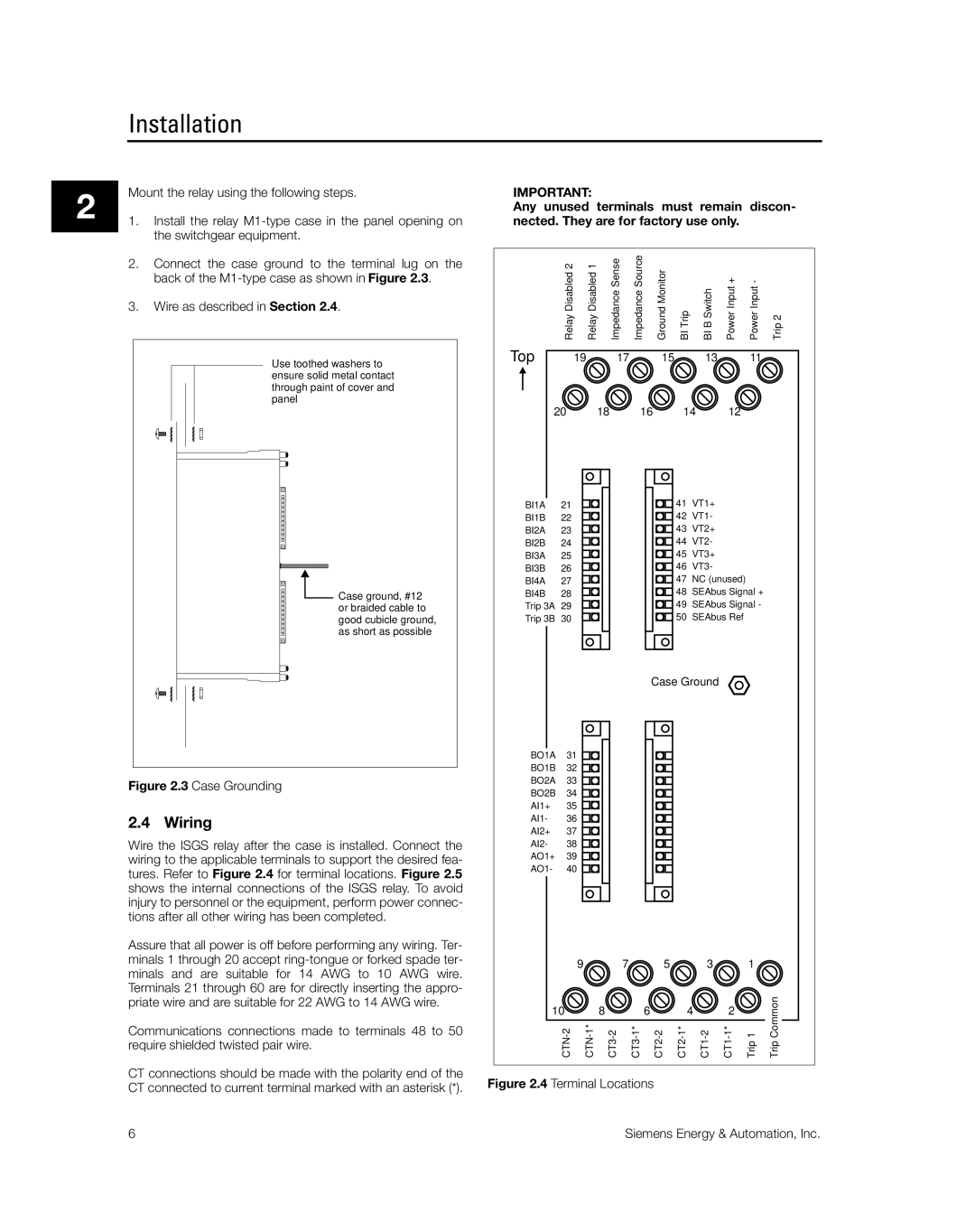
Wire the ISGS relay after the case is installed. Connect the wiring to the applicable terminals to support the desired fea- tures. Refer to Figure 2.4 for terminal locations. Figure 2.5 shows the internal connections of the ISGS relay. To avoid injury to personnel or the equipment, perform power connec- tions after all other wiring has been completed.
Assure that all power is off before performing any wiring. Ter- minals 1 through 20 accept
Communications connections made to terminals 48 to 50 require shielded twisted pair wire.
IMPORTANT:
Any unused terminals must remain discon- nected. They are for factory use only.
| RelayDisabled2 | RelayDisabled1 | ImpedanceSense | ImpedanceSource | GroundMonitor | BITrip | BIBSwitch | PowerInput+ | PowerInput- | Trip2 | |
Top | 19 | 17 |
| 15 |
|
| 13 |
| 11 |
| |
20 |
| 18 | 16 | 14 | 12 |
|
| ||||
BI1A | 21 |
|
|
|
| 41 |
| VT1+ |
|
|
|
BI1B | 22 |
|
|
|
| 42 |
| VT1- |
|
|
|
BI2A | 23 |
|
|
|
| 43 |
| VT2+ |
|
|
|
BI2B | 24 |
|
|
|
| 44 |
| VT2- |
|
|
|
BI3A | 25 |
|
|
|
| 45 |
| VT3+ |
|
|
|
BI3B | 26 |
|
|
|
| 46 |
| VT3- |
|
|
|
BI4A | 27 |
|
|
|
| 47 |
| NC (unused) |
|
| |
BI4B | 28 |
|
|
|
| 48 |
| SEAbus Signal + |
| ||
Trip 3A | 29 |
|
|
|
| 49 |
| SEAbus Signal - |
| ||
Trip 3B | 30 |
|
|
|
| 50 |
| SEAbus Ref |
|
| |
|
|
|
|
| Case Ground |
|
|
| |||
BO1A | 31 |
|
|
|
|
|
|
|
|
|
|
BO1B | 32 |
|
|
|
|
|
|
|
|
|
|
BO2A | 33 |
|
|
|
|
|
|
|
|
|
|
BO2B | 34 |
|
|
|
|
|
|
|
|
|
|
AI1+ | 35 |
|
|
|
|
|
|
|
|
|
|
AI1- | 36 |
|
|
|
|
|
|
|
|
|
|
AI2+ | 37 |
|
|
|
|
|
|
|
|
|
|
AI2- | 38 |
|
|
|
|
|
|
|
|
|
|
AO1+ | 39 |
|
|
|
|
|
|
|
|
|
|
AO1- | 40 |
|
|
|
|
|
|
|
|
|
|
|
| 9 | 7 |
| 5 |
|
| 3 |
| 1 |
|
10 |
| 8 |
| 6 |
| 4 | 2 |
| TripCommon | ||
|
| Trip1 | |||||||||
CT connections should be made with the polarity end of the | Figure 2.4 Terminal Locations | |
CT connected to current terminal marked with an asterisk (*). | ||
|
6 | Siemens Energy & Automation, Inc. |