Hardware Configuration
4 Hardware Configuration
This chapter explains the device startup and how to config- ure the basic ISGS relay parameters. The relay must be con- figured with certain system parameters, such as phase sequence and frequency. In addition, information regarding the manner in which the ISGS relay is connected in the installation must be configured.
All parameter changes require a password. Refer to
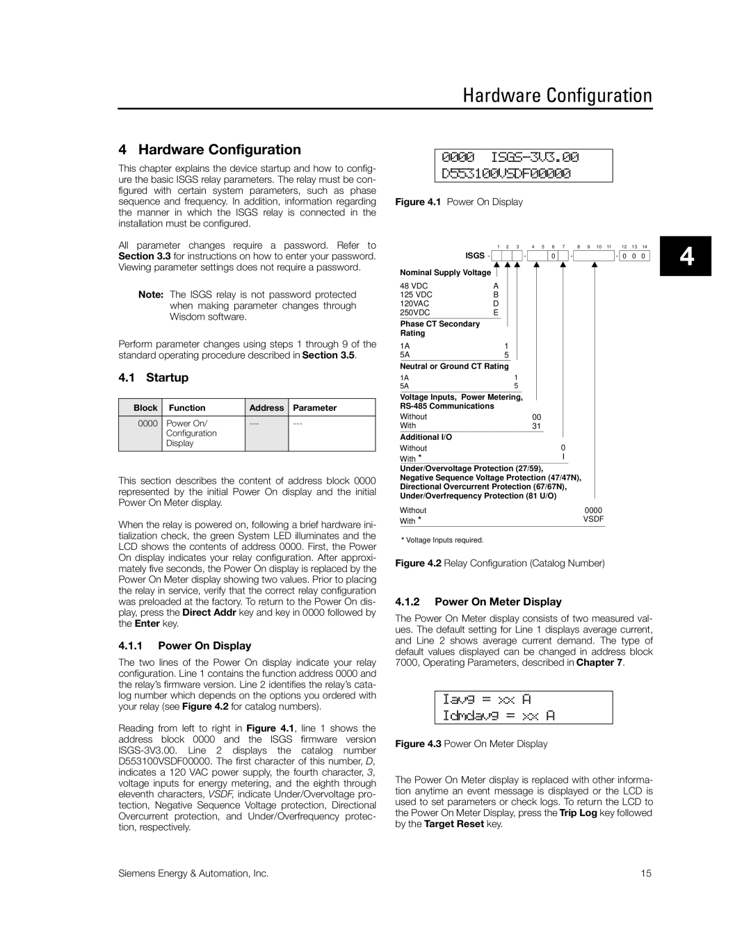
0000 ISGS-3V3.00 D553100VSDF00000
Figure 4.1 Power On Display
1 | 2 | 3 | 4 | 5 | 6 | 7 | 8 | 9 | 10 | 11 |
12 13 14
Section 3.3 for instructions on how to enter your password. Viewing parameter settings does not require a password.
Note: The ISGS relay is not password protected when making parameter changes through Wisdom software.
ISGS -
Nominal Supply Voltage
48 VDC | A |
125 VDC | B |
120VAC | D |
250VDC | E |
Phase CT Secondary Rating
-
0
-
- 0 0 0
4
Perform parameter changes using steps 1 through 9 of the standard operating procedure described in Section 3.5.
4.1 Startup
Block | Function | Address | Parameter |
0000 | Power On/ | ||
| Configuration |
|
|
| Display |
|
|
|
|
|
|
This section describes the content of address block 0000 represented by the initial Power On display and the initial Power On Meter display.
When the relay is powered on, following a brief hardware ini- tialization check, the green System LED illuminates and the LCD shows the contents of address 0000. First, the Power On display indicates your relay configuration. After approxi- mately five seconds, the Power On display is replaced by the Power On Meter display showing two values. Prior to placing the relay in service, verify that the correct relay configuration was preloaded at the factory. To return to the Power On dis- play, press the Direct Addr key and key in 0000 followed by the Enter key.
4.1.1Power On Display
The two lines of the Power On display indicate your relay configuration. Line 1 contains the function address 0000 and the relay’s firmware version. Line 2 identifies the relay’s cata- log number which depends on the options you ordered with your relay (see Figure 4.2 for catalog numbers).
Reading from left to right in Figure 4.1, line 1 shows the address block 0000 and the ISGS firmware version
|
|
|
|
|
|
|
|
|
|
|
|
|
|
|
|
|
|
|
|
|
|
|
|
|
|
1A |
|
|
|
|
|
|
|
|
|
| ||
1 |
|
|
|
|
|
|
|
| ||||
5A | 5 |
|
|
|
|
|
|
|
| |||
|
|
|
|
|
|
|
|
| ||||
Neutral or Ground CT Rating |
|
|
|
|
| |||||||
1A | 1 |
|
|
|
|
|
| |||||
5A | 5 |
|
|
|
|
|
| |||||
|
|
|
|
|
| |||||||
Voltage Inputs, Power Metering, |
|
|
|
|
|
| ||||||
|
|
|
|
|
|
|
|
|
| |||
Without | 00 |
|
|
|
| |||||||
With | 31 |
|
|
|
| |||||||
Additional I/O |
|
|
|
|
|
|
|
|
|
| ||
0 |
|
| ||||||||||
Without |
|
| ||||||||||
With * |
|
|
|
|
|
| I |
|
| |||
Under/Overvoltage Protection (27/59), |
| |||||||||||
Negative Sequence Voltage Protection (47/47N), |
| |||||||||||
Directional Overcurrent Protection (67/67N), |
| |||||||||||
Under/Overfrequency Protection (81 U/O) |
| |||||||||||
Without | 0000 | |||||||||||
With * |
|
|
|
|
|
|
|
| VSDF | |||
* Voltage Inputs required.
Figure 4.2 Relay Configuration (Catalog Number)
4.1.2Power On Meter Display
The Power On Meter display consists of two measured val- ues. The default setting for Line 1 displays average current, and Line 2 shows average current demand. The type of default values displayed can be changed in address block 7000, Operating Parameters, described in Chapter 7.
Iavg = xx A
Idmdavg = xx A
Figure 4.3 Power On Meter Display
The Power On Meter display is replaced with other informa- tion anytime an event message is displayed or the LCD is used to set parameters or check logs. To return the LCD to the Power On Meter Display, press the Trip Log key followed by the Target Reset key.
Siemens Energy & Automation, Inc. | 15 |
