Hardware Configuration
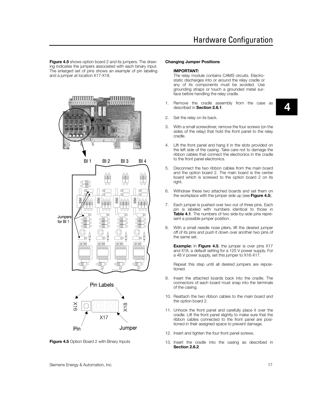
Figure 4.5 shows option board 2 and its jumpers. The draw- ing indicates the jumpers associated with each binary input. The enlarged set of pins shows an example of pin labeling and a jumper at location X17-X18.
350 | 350 | 350 | 350 |
| .22 163 |
|
|
|
| .22 163 |
|
|
|
| .22 163 |
|
|
|
| .22 163 |
|
| |||||||||||||||
|
|
|
|
|
|
|
|
|
|
|
|
|
|
|
|
|
|
|
|
|
|
|
|
|
|
|
|
|
|
|
|
|
|
|
|
|
|
|
|
|
|
|
|
|
|
|
|
|
|
|
|
|
|
|
|
|
|
|
|
|
|
|
|
|
|
|
|
|
|
|
|
|
|
|
|
|
|
|
|
|
|
|
|
|
|
|
|
|
|
|
|
|
|
|
|
|
|
|
|
|
|
|
|
|
|
|
|
|
|
|
|
|
|
|
|
|
|
|
|
|
|
|
|
|
|
|
|
|
|
|
|
|
|
|
|
|
|
|
|
|
|
|
|
|
|
|
|
|
|
|
|
|
|
|
|
|
|
|
|
|
|
|
|
|
|
|
|
|
|
|
|
|
|
|
|
|
|
|
|
|
|
|
|
|
|
|
|
|
|
|
|
|
|
|
|
|
|
|
|
|
|
|
|
|
|
|
|
|
|
|
|
|
|
|
|
|
|
|
|
|
|
|
|
|
|
|
|
|
|
|
|
|
|
|
|
|
|
|
|
|
|
|
|
|
|
|
|
|
|
|
|
|
|
|
|
|
|
|
|
|
|
|
|
|
|
|
|
|
|
|
|
|
|
|
|
|
|
|
|
|
|
|
|
|
|
|
|
|
|
|
|
|
|
|
|
|
|
|
|
|
|
|
|
|
|
|
|
|
|
|
|
|
|
|
|
|
|
|
|
|
|
|
|
|
|
|
|
|
|
|
|
|
|
|
|
|
|
|
|
Figure 4.5 Option Board 2 with Binary Inputs
Changing Jumper Positions
IMPORTANT:
The relay module contains CAMS circuits. Electro- static discharges into or around the relay cradle or any of its components must be avoided. Use grounding straps or touch a grounded metal sur- face before handling the relay cradle.
1.Remove the cradle assembly from the case as described in Section 2.6.1.
2.Set the relay on its back.
3.With a small screwdriver, remove the four screws (on the sides of the relay) that hold the front panel to the relay cradle.
4.Lift the front panel and hang it in the slots provided on the left side of the casing. Take care not to damage the ribbon cables that connect the electronics in the cradle to the front panel electronics.
5.Disconnect the two ribbon cables from the main board and the option board 2. The main board is the center board which is screwed to the option board 2 on its right.
6.Withdraw these two attached boards and set them on the workplace with the jumper side up (see Figure 4.5).
7.Each jumper is pushed over two out of three pins. Each pin is labeled with numbers identical to those in Table 4.1. The numbers of two side-by-side pins repre- sent a possible jumper position.
8.With a small needle nose pliers, lift the desired jumper off of its pins and push it down over another two pins of the same set.
Example: In Figure 4.5, the jumper is over pins X17 and X18, a default setting for a 125 V power supply. For a 48 V power supply, set this jumper to X16-X17.
Repeat this step until all desired jumpers are reposi- tioned.
9.Insert the attached boards back into the cradle. The connectors of each board must snap into the terminals of the casing.
10.Reattach the two ribbon cables to the main board and the option board 2.
11.Unhook the front panel and carefully place it over the cradle. Lift the front panel slightly to make sure that the ribbon cables connected to the front panel are posi- tioned in their assigned space to prevent damage.
12.Insert and tighten the four front panel screws.
13.Insert the cradle into the casing as described in Section 2.6.2.
4
Siemens Energy & Automation, Inc. | 17 |