Control & Communications
6
6.4 Trip Contacts
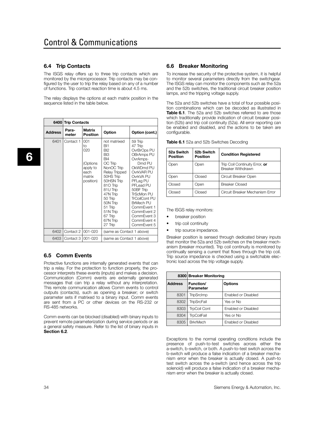
The ISGS relay offers up to three trip contacts which are monitored by the microprocessor. Trip contacts may be con- figured by the user to trip the relay based on any of a number of functions. Trip contact reaction time is about 4.5 ms.
The relay displays the options at each matrix position in the sequence listed in the table below.
6400 | Trip Contacts |
|
| |
Address | Para- | Matrix | Option | Option (cont.) |
meter | Position | |||
6401 | Contact 1 | 001 | not matrixed | 59 Trip |
|
| to | BI1 | 47 Trip |
|
| 020 | BI2 | OvrBrOps PU |
|
|
| BI3 | OBrAmps PU |
|
|
| BI4 | OvrAmps- |
|
| (Options | OC Trip | Dmd PU |
|
| apply to | NonOC Trip | OkWDmd PU |
|
| each | Relay Tripped | OvrkVAR PU |
|
| matrix | 50HS Trip | OvrkVA PU |
|
| position) | 50HSN Trip | PFLag PU |
|
|
| 81O Trip | PFLead PU |
|
|
| 81U Trip | 50BF Trip |
|
|
| 47N Trip | TrScMon PU |
|
|
| 50 Trip | TrCoilCont PU |
|
|
| 50N Trip | BrMech PU |
|
|
| 51 Trip | CommEvent 1 |
|
|
| 51N Trip | CommEvent 2 |
|
|
| 67 Trip | CommEvent 3 |
|
|
| 67N Trip | CommEvent 4 |
|
|
| 27 Trip | CommEvent 5 |
6402 | Contact 2 | (same as Contact 1 above) | ||
6403 | Contact 3 | (same as Contact 1 above) | ||
|
|
|
|
|
6.5 Comm Events
Protective functions are internally generated events that can trip a relay. For the protection to function properly, the pro- cessor interprets these events (inputs) and makes a decision. Communication (Comm) events are externally generated messages that can trip a relay without any interpretation. This remote communication allows Comm events to control outputs (contacts), such as opening a breaker; or switch parameter sets if matrixed to a binary input. Comm events are sent from a PC or other devices on the
Comm events can be blocked (disabled) with binary inputs to prevent remote parameterization during service periods or as a general safety measure. Refer to the list of binary inputs in Section 6.2.
6.6 Breaker Monitoring
To increase the security of the protective system, it is helpful to monitor several parameters directly from the switchgear. The ISGS relay can monitor the components such as the 52a and the 52b switches, the traditional circuit breaker position lamps, and the tripping voltage supply.
The 52a and 52b switches have a total of four possible posi- tion combinations which can be decoded as illustrated in Table 6.1. The 52a and 52b switches referred to are those which traditionally provide indication of circuit breaker posi- tion (52b) and trip coil continuity (52a). All error reporting can be enabled and disabled, and the actions to be taken are configurable.
Table 6.1 52a and 52b Switches Decoding
52a Switch | 52b Switch | Condition Registered | |
Position | Position | ||
| |||
|
|
| |
Open | Open | Trip Coil Continuity Error, or | |
|
| Breaker Withdrawn | |
|
|
| |
Open | Closed | Circuit Breaker Open | |
|
|
| |
Closed | Open | Breaker Closed | |
|
|
| |
Closed | Closed | Circuit Breaker Mechanism Error | |
|
|
|
The ISGS relay monitors:
•breaker position
•trip coil continuity
•trip source impedance.
Breaker position is sensed through dedicated binary inputs that monitor the 52a and 52b switches on the breaker mech- anism (breaker mounted). Trip coil continuity is monitored by continually sensing a current that flows through the trip coil. Trip source impedance is checked using a switchable elec- tronic load across the trip voltage supply.
8300 | Breaker Monitoring | |
Address | Function/ | Options |
| Parameter |
|
8301 | TripSrcImp | Enabled or Disabled |
8302 | TripSrcFail | Yes or No |
8303 | TrpCoil Cont | Enabled or Disabled |
8304 | TrpCoilFail | Yes or No |
8305 | BrkrMech | Enabled or Disabled |
|
|
|
Exceptions to the normal operating conditions include the presence of
34 | Siemens Energy & Automation, Inc. |
