Protective Function Configuration
5
The range of the pickup value (2003) depends on the sec- ondary phase neutral CT rating (1 A or 5 A) and the value is in secondary amperes. The function begins timing when any individual neutral current exceeds the pickup current setting.
Note: The pickup point is 1.06 of the pickup set- ting. Refer also to paragraph on Pickup in Section 5.1.
The Time Dial (2005) used for the selected curve allows the
The Filter (2006) sets the sensing method used by the func- tion in its pickup calculations. The rms filter uses fundamen- tal current plus harmonics, while the fundamental filter ignores harmonics.
Impedance (2007) sets the angle used by this function. It determines the direction of current flow being measured and can be set from 0 to 90 degrees. The directional characteris- tic (line) in the complex impedance plane is shown in Figure 5.2. The directional characteristic is always perpen- dicular to the line impedance vector.
The sensing direction (2008) can be set to forward or reverse. The forward setting allows the directional protection element to pickup on fault current only in the direction of nor- mal power flow.
Each of the two waveform capture buffers (2010 and 2011) can be independently programmed to freeze snapshots on pickup or trip.
The Directional Neutral or Ground Time Overcurrent function is able to actuate any binary output contact on pickup, and any trip or binary output contact on trip.
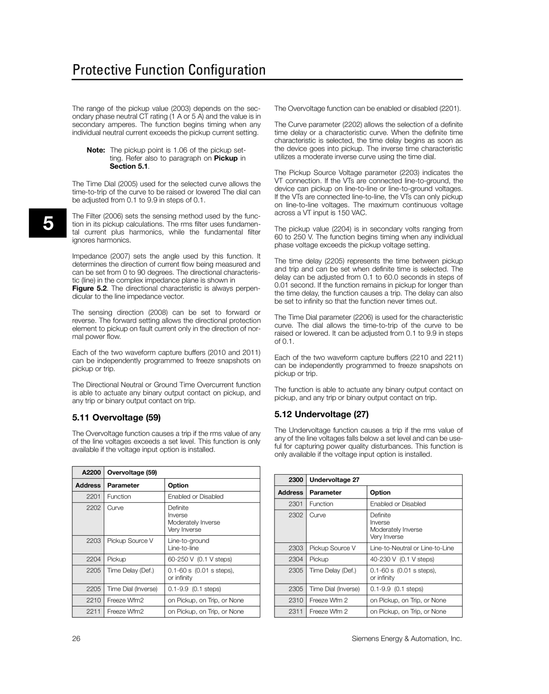
The Overvoltage function can be enabled or disabled (2201).
The Curve parameter (2202) allows the selection of a definite time delay or a characteristic curve. When the definite time characteristic is selected, the time delay begins as soon as the device goes into pickup. The inverse time characteristic utilizes a moderate inverse curve using the time dial.
The Pickup Source Voltage parameter (2203) indicates the VT connection. If the VTs are connected
The pickup value (2204) is in secondary volts ranging from 60 to 250 V. The function begins timing when any individual phase voltage exceeds the pickup voltage setting.
The time delay (2205) represents the time between pickup and trip and can be set when definite time is selected. The delay can be adjusted from 0.1 to 60.0 seconds in steps of
0.01second. If the function remains in pickup for longer than the time delay, the function causes a trip. The delay can also be set to infinity so that the function never times out.
The Time Dial parameter (2206) is used for the characteristic curve. The dial allows the
Each of the two waveform capture buffers (2210 and 2211) can be independently programmed to freeze snapshots on pickup or trip.
The function is able to actuate any binary output contact on pickup, and any trip or binary output contact on trip.
5.11 Overvoltage (59)
The Overvoltage function causes a trip if the rms value of any of the line voltages exceeds a set level. This function is only available if the voltage input option is installed.
A2200 | Overvoltage (59) |
|
|
Address | Parameter | Option |
|
2201 | Function | Enabled or Disabled | |
2202 | Curve | Definite |
|
|
| Inverse |
|
|
| Moderately Inverse | |
|
| Very Inverse | |
2203 | Pickup Source V | ||
|
| ||
2204 | Pickup | (0.1 V steps) | |
2205 | Time Delay (Def.) | (0.01 s steps), | |
|
| or infinity |
|
2205 | Time Dial (Inverse) | ||
2210 | Freeze Wfm2 | on Pickup, on Trip, or None | |
2211 | Freeze Wfm2 | on Pickup, on Trip, or None | |
|
|
|
|
5.12 Undervoltage (27)
The Undervoltage function causes a trip if the rms value of any of the line voltages falls below a set level and can be use- ful for capturing power quality disturbances. This function is only available if the voltage input option is installed.
2300 | Undervoltage 27 |
|
|
Address | Parameter | Option |
|
2301 | Function | Enabled or Disabled | |
2302 | Curve | Definite |
|
|
| Inverse |
|
|
| Moderately Inverse | |
|
| Very Inverse | |
2303 | Pickup Source V | ||
2304 | Pickup | (0.1 V steps) | |
2305 | Time Delay (Def.) | (0.01 s steps), | |
|
| or infinity |
|
2305 | Time Dial (Inverse) | ||
2310 | Freeze Wfm 2 | on Pickup, on Trip, or None | |
2311 | Freeze Wfm 2 | on Pickup, on Trip, or None | |
|
|
|
|
26 | Siemens Energy & Automation, Inc. |
