Functional Overview
Static memory clocking options
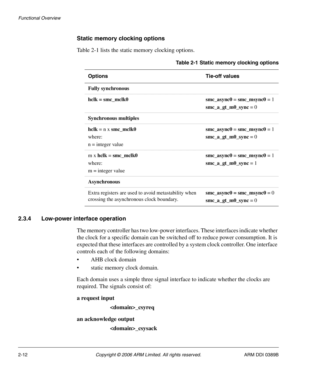
Table 2-1 lists the static memory clocking options.
Table | |
|
|
Options |
|
|
|
Fully synchronous |
|
|
|
hclk = smc_mclk0 | smc_async0 = smc_msync0 = 1 |
| smc_a_gt_m0_sync = 0 |
|
|
Synchronous multiples |
|
|
|
hclk = n x smc_mclk0 | smc_async0 = smc_msync0 = 1 |
where: | smc_a_gt_m0_sync = 0 |
n = integer value |
|
|
|
m x hclk = smc_mclk0 | smc_async0 = smc_msync0 = 1 |
where: | smc_a_gt_m0_sync = 1 |
m = integer value |
|
|
|
Asynchronous |
|
|
|
Extra registers are used to avoid metastability when | smc_async0 = smc_msync0 = 0 |
crossing the asynchronous clock boundary. | smc_a_gt_m0_sync = 0 |
|
|
2.3.4Low-power interface operation
The memory controller has two
•AHB clock domain
•static memory clock domain.
Each domain uses a simple three signal interface to indicate whether the clocks are required. The signals consist of:
a request input <domain>_csyreq
an acknowledge output <domain>_csysack
Copyright © 2006 ARM Limited. All rights reserved. | ARM DDI 0389B |