|
| Chapter 2 | Printer Installation |
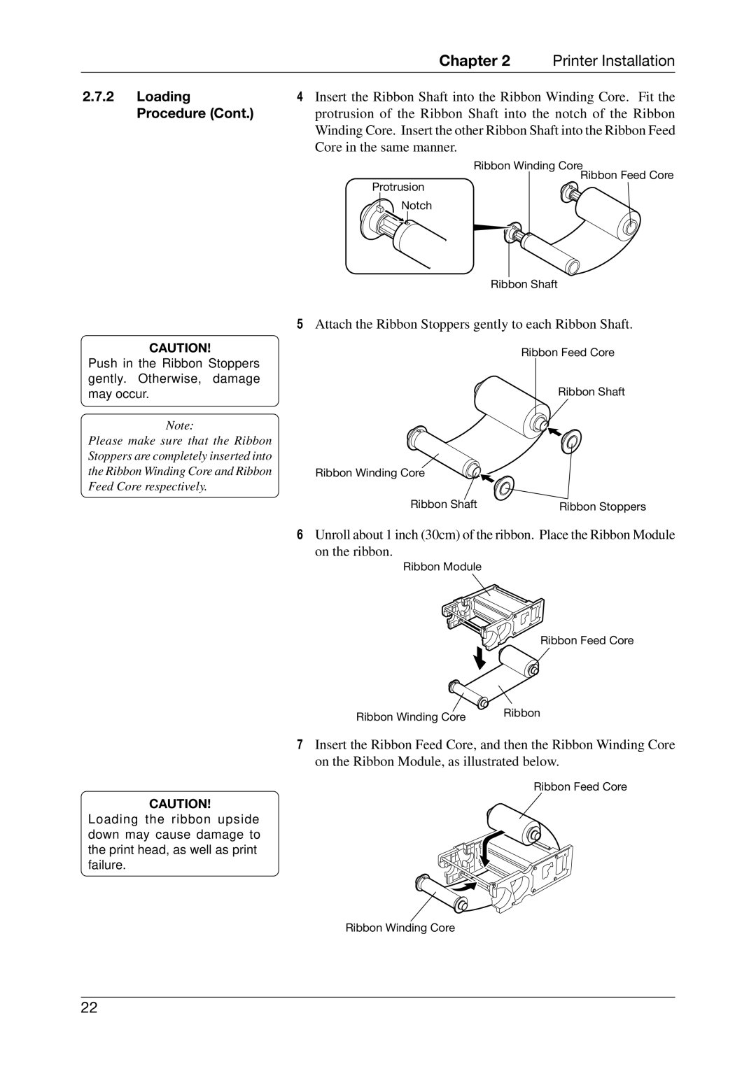
2.7.2 | Loading | 4 Insert the Ribbon Shaft into the Ribbon Winding Core. Fit the | |
| Procedure (Cont.) | protrusion of the Ribbon Shaft into the notch of the Ribbon | |
|
| Winding Core. Insert the other Ribbon Shaft into the Ribbon Feed | |
|
| Core in the same manner. |
|
|
| Ribbon Winding Core | |
|
| Protrusion | Ribbon Feed Core |
|
|
| |
|
| Notch |
|
Ribbon Shaft
CAUTION!
Push in the Ribbon Stoppers gently. Otherwise, damage may occur.
Note:
Please make sure that the Ribbon Stoppers are completely inserted into the Ribbon Winding Core and Ribbon Feed Core respectively.
5Attach the Ribbon Stoppers gently to each Ribbon Shaft.
Ribbon Feed Core
Ribbon Shaft
Ribbon Winding Core
Ribbon Shaft | Ribbon Stoppers |
6Unroll about 1 inch (30cm) of the ribbon. Place the Ribbon Module
on the ribbon.
Ribbon Module
Ribbon Feed Core
Ribbon Winding Core | Ribbon |
|
7Insert the Ribbon Feed Core, and then the Ribbon Winding Core on the Ribbon Module, as illustrated below.
Ribbon Feed Core
CAUTION!
Loading the ribbon upside down may cause damage to the print head, as well as print failure.
Ribbon Winding Core
22