4 Replacement Procedures | 4.12 Top Cover with the Display Assembly |
| M2.5x3.5 black |
| Top cover |
MIC cable
Latch
Speaker extended cable
CN13
CN5005 | Latch |
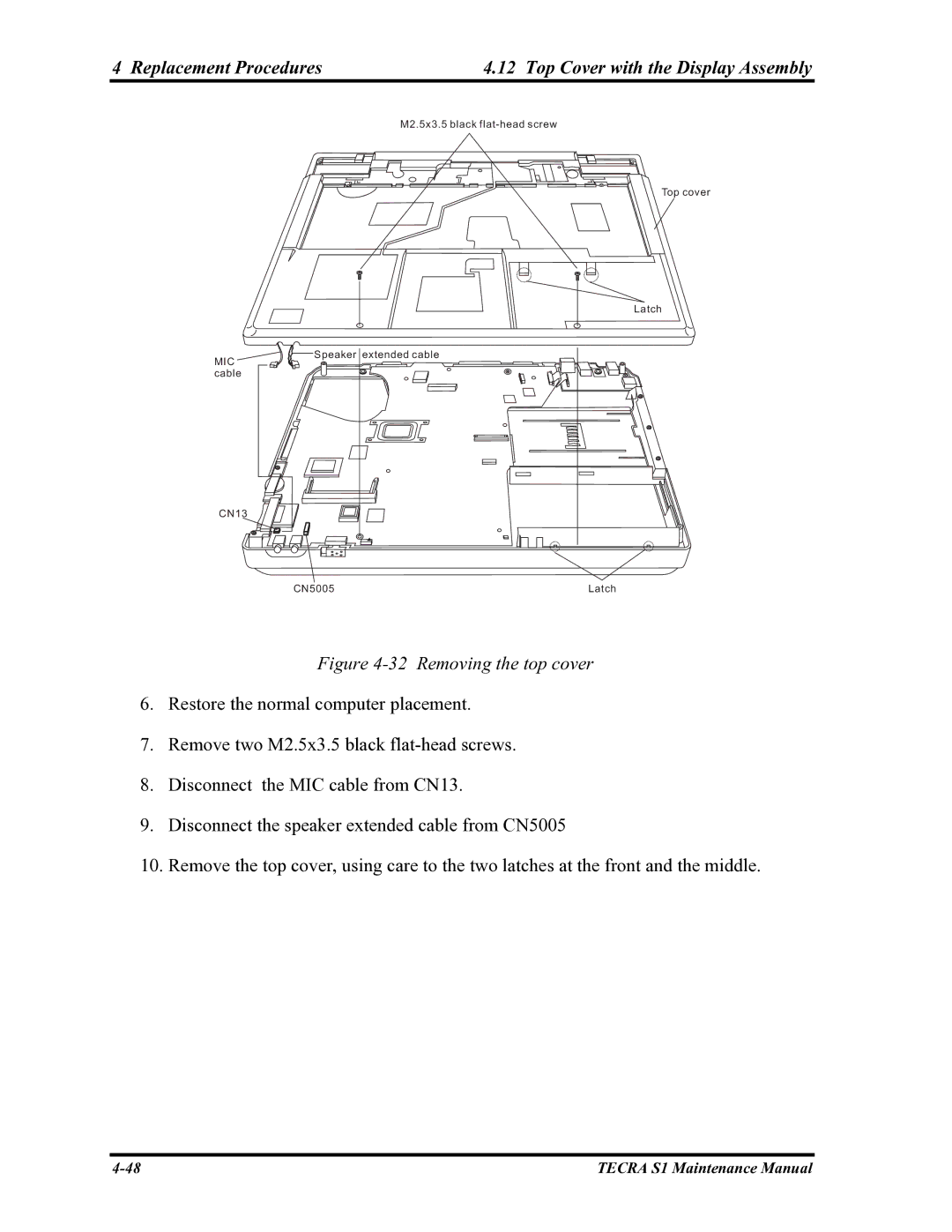
Figure 4-32 Removing the top cover
6.Restore the normal computer placement.
7.Remove two M2.5x3.5 black
8.Disconnect the MIC cable from CN13.
9.Disconnect the speaker extended cable from CN5005
10.Remove the top cover, using care to the two latches at the front and the middle.
TECRA S1 Maintenance Manual |