MES-2110
Page
Intended Audience
About This Users Guide
Customer Support
Syntax Conventions
Document Conventions
Dslam
MES-2110 Computer Server
Firewall
Telephone Router
Safety Warnings
Safety Warnings MES-2110 User’s Guide
Contents Overview
Contents Overview MES-2110 User’s Guide
Table of Contents
Chapter System Details
10.1
Igmp
137
Chapter Command Line Interface 179
Index 229
Table of Contents MES-2110 User’s Guide
Backbone Application
Introduction
Overview
Backbone Application
Bridging Example
Ieee 802.1Q Vlan Application Examples
High Performance Switching Example
Metro Ethernet
Shared Server Using Vlan Example
Metro Ethernet
Ways to Manage the MES-2110
Good Habits for Managing the MES-2110
Desktop Installation Procedure
Hardware Installation and Connection
Installation Scenarios
Mounting the MES-2110 on a Rack
Rack-mounted Installation Requirements
Attaching the Mounting Brackets
Attaching the Mounting Brackets to the MES-2110
Mounting the MES-2110 on a Rack
Mounting the MES-2110 on a Rack
Front Panel
Hardware Overview
Gigabit Ethernet Ports
Console Port
Front Panel Connections
Label Description
Mini-GBIC Slots
Default Ethernet Negotiation Settings
Transceiver Installation
Removing the Fiber Optic Cables
Power Connections Overview
DC Power Connection
AC Power Connection
LEDs
Powering on the MES-2110
LED Descriptions
LED Color Statu Description
Mbps Ethernet network
Green Blinking
Igmp Snooping
Tutorials
Set Igmp Query Mode to Auto
Radius Configuration
Tutorials
Tutorials
Setting Value
MVR Configuration
MVR Tutorial Values
Based802.1q before proceeding
Open the Configuration Igmp Menu MVR screen
Tutorials
Vlan ID Priority
For Pri-Overide, select Enable
Untrusted ARP Inspection
Set Action to Enable and Dhcp Snooping Vlan Mode to All-VLAN
Outgoing Traffic Bandwidth
Frame Tagging Example
Frame Tagging
To configure frame tagging
Tutorials MES-2110 User’s Guide
Introduction
Web Configurator
System Login
Web Configurator Login
Main Screen
Web Configurator Main Screen
Navigation Panel Sub-links Overview
System Details Configuration Mgmt Config System Restart Menu
System Details Configuration Mgmt Config Restart Menu
Web Configurator Screen Sub-links Details
Snmp
Sntp
Dhcp
Navigation Panel Links
Link Description
ARP
Made on the MES-2110 and restart the MES-2110
Saving Your Configuration
Set Up the Administrative Password
Reload the Configuration File
Switch Lockout
Resetting the MES-2110
Resetting the MES-2110 Via the Console Port
System Information Screen
System Details
Board Information Screen
Address, subnet mask and a default gateway IP address
Dhcp Configuration Screen
IP address from a Dhcp server if Dhcp client is enabled
Undo Click this to restore your last saved settings Apply
System Details Dhcp Config Apply
Port Configuration Screen
Configuration
Auto
Truncated in some Web Configurator screens
Disabled
Duplex This indicates the port’s duplex mode Half or Full
Port Status Screen
Manage the MES-2110 via that port
This shows whether auto-negotiation is On or Off
Rmon Status Screen
RX+TX
Configuration Rmon Status
Loop Detection
Switch in Loop State
Loop detection Probe Frame
Loop Detection Screen
Feature
Snmp traps when it shuts down a port via the loop detection
Enabled, the MES-2110 sends probe frames from this port to
Down this port
Loop Detection MES-2110 User’s Guide
Frame Size
Jumbo Frame Configuration Screen
Jumbo Frame
Jumbo Frame MES-2110 User’s Guide
802.1x
Ieee 802.1x Authentication
Guest Vlan
Ieee 802.1x Authentication Process
10.2 802.1x Global Configuration Screen
MES-2110. The key is not sent over the network
10.3 802.1x Radius Server Configuration Screen
Server UDP
Port Number 1812 Server
Before configuring it on each port
10.4 802.1x Port Configuration Screen
Guest Vlan
Reauthenticat
Clients for port access
10.5 802.1x Radius Server Configuration Screen
Radius and TACACS+
Technical Reference
Supported Radius Attributes
Radius vs. TACACS+
Attributes Used for Authenticating Privilege Access
Attributes Used for Authentication
Attributes Used for Accounting
Attribute Start INTERIM-UPDATE Stop
Radius Attributes Exec Events via Console
Radius Attributes Exec Events via Telnet/SSH
Radius Attributes-Exec Events via
Attributes Used for Accounting Ieee 802.1x Events
802.1x MES-2110 User’s Guide
STP Terminology
Bridge
STP Path Costs
Link Recommended Allowed Speed Value Range
Path 16Mbps 40 to Cost 100Mbps 10 to 1Gbps 10Gbps
How STP Works
STP Port States
Bridge Configuration Screen
STP Port States
Port Description State
Are done configuring
Rstp System Configuration Screen
You select Rstp 802.1W in the Ring Protocol field
Tunnel port receives Bridge Protocol Data Units Bpdu
Determines Hello Time, Max Age and Forwarding Delay
Same priority, the switch with the lowest MAC address will
Root Bridge Information
List box
As a general rule
Allowed range is 4 to 30 seconds
Selected from among the MES-2110 ports attached to
Network. The allowed range is 6 to 40 seconds
Cost 1~65535 Enter the port’s path cost
Spanning Tree Port Configuration
255 and the default value is
P2P
Tpid
Introduction to Ieee 802.1Q Tagged VLANs
User Priority
CFI Vlan ID
Ieee 802.1Q Vlan Terminology
Forwarding Tagged and Untagged Frames
Vlan Term Description Parameter
Vlan
Vlan Type Use this to set the MES-2110 to Port-Based or Tag
Vlan Type Screen
Port-Based Vlan Screen
Then you cannot access the web configurator from a computer
Port-Based Vlan Configuration
100
Connected to this port
Vlan Stacking
Tag-Based Vlan Screens
Vlan Stacking Example
101
102
Vlan Stacking Port Roles
103
Vlan Tag Format
Vlan Tag Format
Type Priority
104
Frame Format
Single and Double Tagged 802.11Q Frame Format
802.1Q Frame
SP Tpid
Vlan Stacking Configuration Screen
105
Spvid
106
Pvid
Tag-Based Port Information Screen
107
Enter the Vlan ID from 1-4094 that you want to configure
Tag-Based Port Configuration Screen
108
Select whether you want to Add or Modify a Vlan ID
109
Management Vlan Screen
Management Vlan This is the current management Vlan
Unless your current access belongs to the new Vlan
110
111
Bandwidth Control Setup
Bandwidth Control
112
113
Broadcast Storm Control Setup
Broadcast Storm Control
Storm Control Status
Storm Control Configuration
114
115
Port Mirroring Setup
Port Mirroring
Select the monitor port number from the list
Volatile memory when you are done configuring
116
117
Link Aggregation
Dynamic Link Aggregation
Link Aggregation ID Peer Switch
Link Aggregation ID Local Switch
Static Trunking Example
Link Aggregation ID
119
Link Aggregation Setting
Lacp
Link Aggregation Control Protocol
120
MAC
Lacp Link Status
121
122
123
IP Multicast Addresses
Igmp Snooping
124
Igmp Configuration
Igmp Snooping and VLANs
Igmp Vlan
125
126
Igmp Vlan Query Mode
127
Igmp Status
MVR Overview
How MVR Works 128
Types of MVR Ports
MVR Modes
129
General MVR Configuration
Select Dynamic to send Igmp reports to all MVR source ports
Disable to turn this feature off
130
131
MVR Group Configuration
132
Group Configuration
Drop-down list box
MVR Group Status
133
MVR Configuration Example
134
135
MVR Group Configuration Example
136
Dhcp Relay Agent Information
Dhcp Relay Configuration
137
Relay Agent Information
138
Dhcp Relay Configuration
Bytes This is the Vlan that the port belongs to
To a Dhcp server
Option82 Information
139
140
141
IP Source Guard
142
Dhcp Snooping Overview
143
Dhcp Snooping Configuration
Dhcp requests will not succeed
144
145
Mode VLANs or specific VLANs to Dhcp servers Dhcp Snooping
Dhcp Binding Table
Ddhhmm
146
147
Configuring ARP Inspection
ARP Inspection Screen
Addresses permanently
148
149
150
151
MAC
152
MAC Table Status Screen
MES-2110 or static manually configured
Undo Click this to load your last saved settings Apply
Lock MAC Address Learning Screen
153
154
MAC Filter Configuration Screen
Port This is the port number Lock
To activate MAC address learning on the port
155
Addresses may access port 2 at any one time. a sixth device
MAC Limit Configuration Screen
156
Aged out. MAC address aging out time can be set in the MAC
157
QoS Base Configuration Screen
QoS
158
Configuring the Base Configuration Screen
159
160
802.1p Priority Table
IP Dscp Priority Table
Tag Priority Table
161
Number This is the Ieee 802.1p priority level Priority
162
Configuration QoS Menu IP Dscp Priority
163
Priority Override Configuration Screen
164
165
Mgmt Config and System Restart Menu
Serial Port Configuration Screen
166
Snmp Configuration Screens
Command Description
Snmp Commands
Snmp Communities Screen
IP Trap Manager Screen
Traps to
Sntp Screen
168
169
170
Alarms and Logs
Syslog
171
Characters using characters found on a standard keyboard
User Configuration Screen
User Password
172
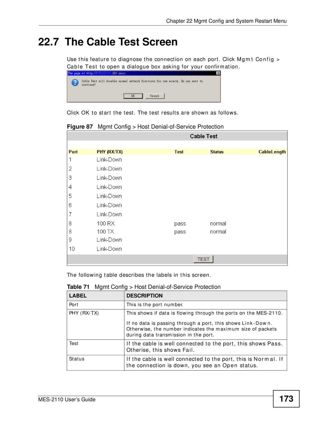
PHY RX/TX
Cable Test Screen
173
Test
Host DoS Protection
174
Fields below
Port Abnormal Traffic Detection Screen
175
176
Upgrading the Firmware
177
Managing the Configuration File
178
Restarting the System
Setting Default Value
Command Line Interface
Console Port Management
Logging
Command / Keys Description
Using Shortcuts and Getting Help
Saving Changes
180
Exit Command
Command Modes
Basic Commands
Logging Out
182
Basic Commands
183
Privileged Command Mode
Privileged Commands
184
Command line interface
Make while using the MES-2110
185
Permanently save any changes you
Configuration Mode Commands
Configuration Mode
186
Ancillary Trigger Description
187
188
189
190
Address over Telnet
191
192
193
Igmp Snooping Example
194
Radius Configuration Example
MVR-Configuration Mode Commands
MVR Mode
This command to work
195
196
MVR Command Example
197
Vlan Mode
Vlan Mode Commands
198
Interface Mode
Vlan ID Priority Example
199
Interface Mode Commands
200
201
Port, the port must allow frames
202
Bytes 1522 bytes + 4 bytes for
Second tag to pass through it
Untrusted ARP Inspection Example
Sets the service provider Vlan ID of the current Ports
Outgoing Traffic Bandwidth Limit Example
203
204
Frame Tagging Examples
205
206
207
Troubleshooting
Power, Hardware Connections, and LEDs
208
MES-2110 Access and Login
Advanced Suggestions
209
Pop-up Windows, JavaScript and Java Permissions
210
211
MES-2110 Configuration and Console
212
My changes in the Web Configurator keep getting overwritten
213
214
Hardware Specifications
Product Specifications
Specification Description
215
216
Firmware Specifications
Feature Description
217
Standard Description
218
Standards Supported
219
Installing a Fuse
Removing a Fuse
220
221
Common Services
Name Protocol Ports Description
Commonly Used Services
222
223
224
225
Copyright
Certifications
FCC Warning CE Mark Warning
226
227
ZyXEL Limited Warranty
228
229
Index
230
Password 58 path cost 89, 93 port authentication
MVR 127 configuration
231
TACACS+
232
Weighted round robin scheduling