Modero CV7
AMX Limited Warranty and Disclaimer
FCC Information
Page
Table of Contents
Panel Calibration
Upgrading Modero Firmware
Programming 135
Appendix B Wireless Technology 197
Table of Contents Modero Widescreen Touch Panels
FG2258-01K
CV7 7 Widescreen Video Touch Panel Kits
FG2258-02K
NXT-CV7
Specifications for 7 Widescreen Video Touch Panels
CV7 Specifications
Rear Panel Components
Using USB with a Virtual Master section on page 53 for more
Front Panel Components
Cont
Included Accessories
Button Assignments
Operating / Storage
USB
CV7 Panels Connector Layout
NXA-AVB/ETHERNET Breakout Box FG2254-10
Product Specifications
NXA-AVB/ETHERNET Specifications
Panels only
Installing the NXA-AVB/ETHERNET
Rear Components
Audio In Right Channel
Wiring the NXA-AVB/ETHERNET connectors and cables
Wiring the NXA-AVB/ETHERNET for Balanced Audio
Wiring the NXA-AVB/ETHERNET for Unbalanced Audio
Modero Table Top Cable CA2250-50
Modero Table Top Cable Specifications
Connectors
Modero Table Top Cable Wiring Table
Wiring information for the Modero Table Top cable
Wire Connector
Maximum Table Top Cable Lengths for Modero Panels
Connector #1 Element #1 Binder Element #2
802.11b Wireless Interface Card Specifications
NXA-WC80211B/CF 802.11b Wireless Card FG2255-03
NXA-WC80211GCF 802.11g Wireless Card FG2255-07
NXA-WC80211GCF Specifications
Radio Technology
Information
Receiver Sensitivity
Standard Conformance Ieee 802.11b
NXA-CFSP Compact Flash FG2116-3x
Optional Compact Flash Upgrades
Remove the existing NXT Outer Housing
Before Upgrading the Wireless Card Read This
Installation and Upgrade of the Internal NXT Components
Do not Remove these screws
Removal of the outer housing and wireless card location
Install the Compact Flash Memory card upgrade
Removing/installing a Compact Flash Memory card
Install the new 802.11g CF Card and Antenna
Close and Resecure the NXT Panel Enclosure
Remove the existing NXD Outer Housing
Installation and Upgrade of the Internal NXD Components
Close and Resecure the NXD Panel Enclosure
Install the new Compact Flash Memory card NXD
Install the new 802.11g Wireless Compact Flash card NXD
Power Voltage
NXT-BP Power Pack FG2255-10
NXT-BP Specifications
Checking the NXT-BP charge
NXA-BASE/1 Battery Base Kit FG2255-05K
NXA-BASE/1 Specifications
Front
Installing an NXT-BP into the NXA-BASE/1
Installing the NXA-BASE/1 below an NXT-CV7 Panel
Back
Charging the NXT-BP using the NXA-BASE/1
NXT-CHG Battery Charger Kit FG2255-50K
Powering the NXT-CHG
NXT-BP and NXT-CHG Specifications
Green Solid
Reading the NXT-CHG LED Indicator
Charging the NXT-BP batteries using the NXT-CHG
Recalibrating the batteries
Unpacking the Panel
Installing the Internal Components
Installing the No-Button Trim Ring
CV7 Panel/enclosure Button latch Trim Ring
Removing the No-Button Trim Ring
Installing the Button Trim Ring
Installer Leave a GAP Between the Stud and ROUGH-IN BOX
Pre-Wall Installation of the Rough-In Box
Installing the NXD panel within a Rough-In Box
Installation of an NXD Touch Panel
Faceplate/Trim Ring Default Faceplate comes with buttons
Installing the NXD into drywall using Expansion Clips
NXD-CV7 Wall Mount panel dimensions using expansion clips
Installation
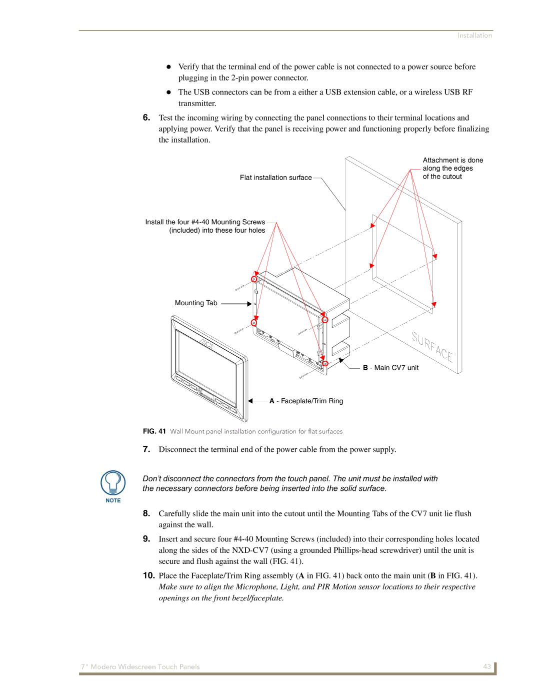
Installing the NXD into a Flat Surface using #4 screws
Along the edges
Installation
Wiring a power connection
Wiring Guidelines for the CV7 Panels
Preparing captive wires
Ethernet/RJ-45 Port Connections and Wiring
Audio/Video Port Connections and Wiring
Pin Wire Color Function Polarity
Audio/Video RJ-45 Pinout Information
Pin Signals Connections Pairing Color
USB Port Connecting and Using Input Devices
Ethernet RJ-45 Pinouts and Signals
Installation Modero Widescreen Touch Panels
Calibrating the Modero Panel
Panel Calibration
Touch Panel Calibration Screens
Testing your Calibration
Modero Setup and System Connection
Configuring Communication
Modero connection information
Confirm the Installation of the USB Driver on the PC
Configuring and Using USB with a Virtual Master
Setup the Panel and PC for USB Communication
To setting up a USB connection to the panel
Device Manager dialog showing USB device
Confirm and View the current AMX USB device connections
Detection Icon
Assigning Communication Settings for a Virtual Master
IP Routing
Wireless Settings Page Wireless Access Overview
Hot Swapping
Configuring a Wireless Connection
Wireless communication using a Dhcp Address
Configure the Panel’s Wireless IP Settings
Using the Site Survey tool
Wireless communication using a Static IP Address
Site Survey
Configure the Card’s Wireless Security Settings
Required Information
Configuring Communication
802.11b wireless card
These WEP Key identifier values must match for both devices
WEP Passphrase Keyboard
Configure the Panel’s Wired IP Settings
Configuring a Wired Ethernet Connection
Information populating these fields is identical
Configure an Ethernet Connection Type
Choose a Master Connection Mode Setting
Before beginning
Ethernet
Configuring Communication
Resides on the same Subnet as itself
G4 Web Control
Using G4 Web Control to Interact with a G4 Panel
Configuring Communication
Using your NetLinx Master to control the G4 panel
Web Control VNC installation and Password entry screens
Configuring Communication
Upgrading the Modero Firmware via the USB port
Configure the panel for a USB Connection Type
Prepare NetLinx Studio for communication via the USB port
Default Modero panel value is
Confirm and Upgrade the firmware via the USB port
Using USB for a Virtual Master transfer
Prepare the Master for communication via an IP
Upgrading the Modero Firmware via Ethernet IP Address
Prepare the panel for communication via an IP
NetLinx Workspace window showing connected Modero panel
Verify and Upgrade the panel firmware via an IP
Selected Firmware file
Setup Navigation Button Elements
Setup Navigation Buttons
Setup Page Elements
Setup
Timeout
Display/Panel Timeout
Connection Status
Inactivity Page Flip
Project Information Page Elements
Project Information
Panel Information Page Elements
Panel Information
Time & Date Setup
Time Date Refresh/Set
Time & Date Setup Page Elements
Time Display fields
Date Display fields
Volume Page Elements
Volume
Master Volume
Default Panel Sounds
Video Adjustment
Protected Setup
Supported sampling rates for WAV
Supported WAV Sampling Rates
Video Setup Page Elements
Battery Base
Low Battery Warning
Battery Base Page Elements
This value can never exceed the Low Battery Warning value
Charge Status
Battery Status fields
Protected Setup Navigation Buttons
Set on the Setup page. This extends the battery usage time
Limit
Protected Setup Navigation Button Elements
Protected Setup
Reboot Panel
Protected Setup Page Elements
System Recovery
Device Number
G4 Web Control
Protected Setup page-System Recovery confirmation dialog
Remaining fields are configured
G4 Web Control Settings
G4 Web Control Timeout
G4 Web Control Page Elements
Sensor Setup Page Elements
Sensor Setup
Light Sensor
Dim Mode Minimum
Light Level field
Motion Sensor
Wake Panel On Motion Sense
Password Setup Page Elements
Password Setup
Panel Password
Change
Calibration
Wireless Settings
Wireless Settings Page Elements
Wireless Security Support
802.11b Wi-Fi CF card
802.11g Wi-Fi CF card
Address
IP Settings
Access Point MAC
Following fields are required Ssid and Password/Pass Phrase
Wireless Security
EAP-PEAP EAP-TTLS EAP-TLS EAP-LEAP
Following fields are required SSID, Identity, and Password
Site Survey
Password
RF Link Info
Communication quality
Wireless Settings Page Security Options Open Clear Text
Wireless Settings Page Security Options Overview
Wireless Security Open Clear Text Settings
Save/Cancel
Wireless Security Static WEP Settings
Wireless Settings Page Security Options Static WEP
WEP 64 / WEP
Bit Key Size
WEP Keys
Wireless Security Static WEP
Default Key
Current Key
Wireless Settings Page Security Options WPA-PSK
Authentication
Password/Pass Phrase
Wireless Settings Page Security Options EAP-LEAP
Wireless Security WPA-PSK Settings
Identity
Wireless Security EAP-LEAP Settings
Password
EAP-LEAP sample Cisco System Security
Wireless Settings Page Security Options EAP-FAST
Anonymous Identity
Wireless Security EAP-FAST Settings
PAC File Location
Disabled manual
Been Disabled
Wireless Settings Page Security Options EAP-PEAP
EAP Security’s Using Server Certificates Overview
Ssid Service Set Identifier
Wireless Security EAP-PEAP Settings
Wireless Security EAP-PEAP
Wireless Settings Page Security Options EAP-TTLS
Wireless Settings page EAP-TTLS security method
Wireless Security EAP-TTLS Settings
This field is optional and can be left blank
MSCHAPv2 default because its the most common
Wireless Security EAP-TLS Settings
Wireless Settings Page Security Options EAP-TLS
Private Key
Private Key password
Client Certificate
Client Certificate Configuration
Client certificate configuration
Certificates and their Extensions
Certificate Type Possible File Extensions
Certificate Types Supported by the Modero Firmware
System Settings
System Settings Page Elements
Master Connection
Full Duplex
134 Modero Widescreen Touch Panels
Commands
Commands
Button Assignments
@APG
@PDR
@DPG
@PHE
@PHP
Deactivate a
Close all popups on Page1
Deactivates the popup page ’Popup1’ on the Main Example
Deactivates the popup page ’Popup1’ on the current
@PPN
@PPM
@PPT
@PPX
@PST
@PSE
@PSP
Ppon
Ppof
Ppog
RGB triplets and names for basic 88 colors
Programming Numbers
RGB Values for all 88 Basic Colors
Index No Name Red Green Blue
142 Modero Widescreen Touch Panels
Font ID # Font type Size
Default Font Styles and ID Numbers
Font styles and ID numbers
Border styles
Border styles
TPD4 Border Styles by Name
Modero Widescreen Touch Panels 145
Button Commands
Button Commands
ANI
APF
Sendcommand Panel,BAU-520,1,00770062
Sendcommand Panel,BAT-520,1,Enter City
BAT
BAT-vt addr range,button states range,new text
BCF
BCB
BFB
BCT
BDO
BLN
BIM
Entry is required
BMC
Sendcommand Panel,BMC-150,1,1,315,1,%BR%FT%TX%BM%IC%CF%CT
BMF-vt addr range,button states range,data
BMF
BMF
BML
BMI
BMP
BNC
BOP
BNN
BNT
BPP
BOR
BOS
BSF
BRD
BSM
BSO
BVN
BVL
BVP
BVT
DPF
CPF
ENA
FON
GIV
GDI
GLH
GLL
GRU
GRD
GSC
GSN
JSI
ICO
JSB
MBT
JST
Pass data
MDC
TEF
TEC
Effect names
TXT
Sendcommand TP,UNI-1,0,0041
Sendcommand Panel,UNI-500,1,0041
UNI
UNI-vt addr range,button states range,unicode text
Text Effects
Text Effect Names
Defineevent
Button Query Commands
Custom Event Fields
Button Query Commands
Field Description
?BCB
?BCT
?BCF
?BOP
?BMP
?BWW
?BRD
?ICO
?FON
?JSI
?JSB
?TEC
?JST
Send Command Panel,?TXT-529,1
Send Command Panel,?TEF-529,1
?TEF
?TEF-vt addr range,button states range
Panel Runtime Operations
Panel Runtime Operation Commands
@AKR
@AKP
Beep
Brit
@EKP
Setup
Pkeyp
@PKP
@TKP
@SOU
Tpageon
Tpageoff
Input Commands
Input Commands
CAL
KPS
Decimal numbers Hexidecimal values Virtual keystroke
Embedded codes
Embedded Codes
Panel Setup Commands
Panel Setup Commands
Dynamic Image Commands
Dynamic Image Commands
RAF-resource name,data
Troubleshooting Information
My Battery Base page doesn’t
Symptom Solution Updated my panel firmware but
My NXT-BP battery pack is
Life indicator
Connecting
Symptom Solution
Was using the power from PSN
When I connected my
NXA-BASE/1 connected to a pow
My battery from within an
Ered panel
My WEP doesn’t seem to be
Only one shows up
Connected to my System Master
After downloading a panel file or
Behaves strangely
Troubleshooting 190 Modero Widescreen Touch Panels
Bargraph Text Code Inputs
Text Formatting Codes for Bargraphs/Joysticks
Formatting Code Operations
Example
Input mask character types
Text Area Input Masking
Character Types
Character Masking Rule
Input mask next field characters
Input mask ranges
Input mask operations
Input mask literals
Common Name Input Mask
Input mask output examples
Output Examples
Special escape sequences
URL Resources
Escape Sequences
Sequence Panel Information
Appendix a 196 Modero Widescreen Touch Panels
Overview of Wireless Technology
Appendix B Wireless Technology
802.1x
Terminology
Tkip
WPA2
EAP characteristics
EAP Authentication
EAP Method Characteristics
Method Credential Type Authentication Pros Cons
EAP security method in process
EAP communication overview
AMX Certificate Upload Utility
Configuring your G4 Touch Panel for USB Communication
204 Modero Touch Panels
How to Upload a Certificate File
206 Modero Touch Panels
Appendix B Wireless Technology Modero Touch Panels 207
Appendix B Wireless Technology 208 Modero Touch Panels
Appendix Modero Widescreen Touch Panels 209
It’s Your World Take Control