Catalog No Rev.C. October
ATM Switch
Avaya M770 ATM Switch User’s Guide
Contents
Contents
Avaya M770 ATM Switch User’s Guide Iii
Contents
Contents
Contents
166
LEC
Viii Avaya M770 ATM Switch User’s Guide
Contents
Contents
Contents
Xii Avaya M770 ATM Switch User’s Guide
Avaya M770 ATM Switch User’s Guide Xiii
303
Virtual Circuits and Virtual Paths 301 Virtual Ports 302
List of Commands in the Command-line Interface
List of Commands in the Command-line Interface
III
List of Commands in the Command-line Interface
Introduction
About the Avaya M770 ATM Switch
Related Documents
Supported Modules
Master Agent and Sub Agent
Hardware Features
Features List
M15-155F/SF/MS module features
M3-622F/SF module features
PGL/LGN
Software Features
Lane Server MIB Private MIB DS3 MIB RFC
SONET/SDH MIB RFC Pnni MIB LEC MIB
Operational Standards
Supported Standards
ATM Forum Standards
Chapter Introduction Avaya M770 ATM Switch User’s Guide
Managing an Avaya M770 ATM Switch
Powering up the Avaya M770 ATM Switch
Getting Started
Management from a local or remote console
Management from a network management station
Setup Procedures on an Avaya M770 ATM Switch
Setting the IP address
Setting the virtual port to its default configuration
ATM Port Configuration
Connecting to a device, supporting Ilmi
Connecting to a device not supporting Ilmi
Routing Configuration
Pnni Configuration
Flat Pnni Configuration
Configuring Hierarchical Pnni
Connecting to another ATM switch which doesn’t support Pnni
M15-155s8//route pnni config admin set level-x+12-5 up
Setting up LAN Emulation
Example for Lane Configuration
Recommended Redundant Lane Services Setup
To check if any Clients registered with the LES elan1 type
Support for Luni
Getting Started Avaya M770 ATM Switch User’s Guide
Getting Connected
How to Use the Command-line Interface
Command Description
How the Command-line Interface Works
Returns you to the root of the hierarchy
Returns you to the previous level in the hierarchy
Command hierarchy
Master Agent and Sub Agent Commands
Output pport
Conventions used to describe commands
Output
Using the on-line help
M15-155s8/help address esi
Setting passwords for local/remote connections
To delete a password
Enter the old password and press Enter for the new password
Managing the Sub Agents
Operational
Switch Summary Information
ELAN5
Parameters
Configuring the Avaya M770 ATM Switch Address Information
Viewing the End System Identifier ESI
Viewing Avaya M770 ATM Switch IP address information
Parameters prefix
Viewing or changing the switch prefix
Setting the switch prefix to its default value
Resetting the saved switch prefix
Output Done
Viewing or changing the IP time server address
Using Ping
IP ARP cache entries
Managing the IP Cache
Connection Admission Control CAC
Allocating VBR bandwidth according to the Sgcac algorithm
Allocating VBR bandwidth according to the PCR
Viewing VBR bandwidth allocation method
Listing Information About All Physical Ports
Managing Physical Ports
Managing Physical Ports
Output from the pport show command
VPC VPI
Displaying counter information for all physical ports
Displaying Counter Information for a Physical Port
Displaying counter information for DS3 physical ports
Pess
Pses
Link far end interval counters for
Displaying Plcp counter information for DS3 physical ports
Disabling a Physical Port
Setting Physical Port Parameters
Enabling a Physical Port
Parameter
Configuring payload scrambling
Specifying the framing mode for a port
Parameters pport id
Configuring transmit rate limit for the M15-155 module
Specifying a cable length for a DS3 port
Specifying a mapping mode for a DS3 port
Specifying the Tx Clock source for a DS3 port
Specifying loopback type for a DS3 port
Resetting Parameters on a Physical Port
Managing Virtual Ports
Showing Virtual Port Information
Listing information about virtual ports
Managing Virtual Ports
Chapter Managing Virtual Ports
Output from the vport show command
Output from the vport show config command
Example Output
Listing the status information for all virtual ports
Output from the vport show status command
Output from the vport show vpivciranges command
Listing bandwidth information for all virtual ports
To control shaping use the vport create command Command
Configuring Virtual Ports
Creating a virtual port
Traffic shaping for DS3 virtual ports
To enable a virtual port, use the vport enable command
To delete a virtual port, use the vport delete command
Deleting a virtual port
Disabling a virtual port
Disabling Ilmi on a virtual port
Managing Ilmi
Disabling Ilmi polling on a virtual port
Disabling Ilmi multiple registration
Enabling Ilmi on a virtual port
Enabling Ilmi polling on a virtual port
Enabling Ilmi multiple registration
Resetting the Ilmi version on a virtual port
Setting the Ilmi version on a virtual port
Setting the signalling profile parameter
Setting Virtual Port Parameters
Parameters vport
Setting the stack type parameter
Setting the signalling Vpci base
Setting the signalling Vpci range
Setting the signalling VPC VPI range
Setting the VPI range on a root virtual port
Setting the signalling VCI range
Parameters vport id
Setting the Qsaal wait parameter on a virtual port
Resetting the signalling profile parameter
Resetting Virtual Port Parameters
Resetting the signalling VPC VPI range
Resetting the stack type parameter
Resetting the signalling VCI range
Resetting the signalling Vpci range
Resetting the Waitqsaal parameter
Resetting the VPI range
Setting the managing probe method for proprietary features
Displaying the method of probing for proprietary features
Managing the Probe Method
Virtual port signalling information
Virtual Port Signalling Information
Chapter Managing Virtual Ports
Signalling Statistics
Setup
Q93B Statistics
Addpartyreject
Count of currently active calls and parties
Qsaal Statistics
Managing Virtual Ports
Listing switched virtual circuits
Resetting signalling statistics
Managing Connections
Listing all virtual circuits
Scat
Listing permanent virtual circuits
RES
Viewing Ilmi information for a virtual port
OSI Nsap
Managing Virtual Ports
Managing Virtual Ports Avaya M770 ATM Switch User’s Guide
Managing Module Hardware
Managing Modules
Viewing the Clock Source Ports
Managing Packet Discard Thresholds for a Module
OC-3 Modules M15-155F/SF/MS
Changing the packet discard thresholds for modules
Displaying the packet discard threshold for modules
Managing the speed for the serial port
Managing the number of VPI and VCI bits
Parameters vpibit
Managing VPI range for VP switching
Managing Trunk ID range for P2MP PVCs
Parameters maxTrunkId
100 Avaya M770 ATM Switch User’s Guide
Permanent Virtual Connections PVCs and PVPs
Managing Permanent Virtual Connections PVCs and PVPs
Managing PVC connections
Creating a Point-to-Point PP PVC connection
Creating a PVC connection
Creating a Point-to-Multipoint PMP PVC connection
Use Either
Freeing a PVC connection
VCL2
Listing the current PVC connections
Disabling a PVC connection
Listing all the VCLs
Enabling a PVC connection
PVC
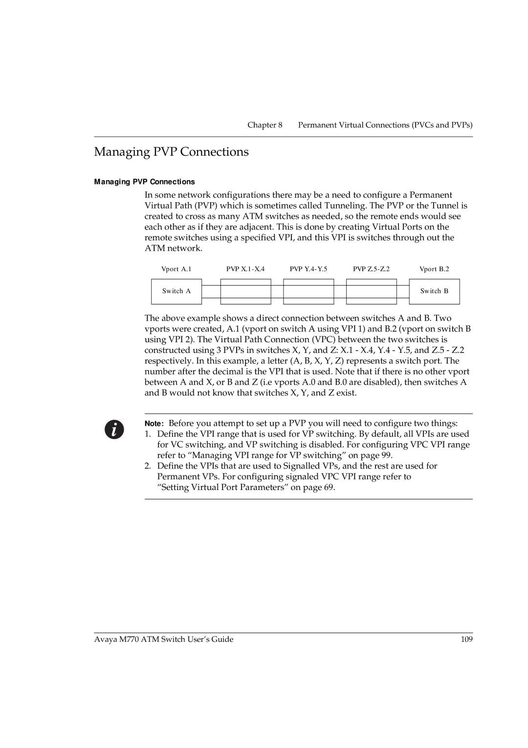
Managing PVP Connections
Managing PVP Connections
Parameters vpl1index
Creating a PVP connection
Listing the current PVP connections
Freeing a PVP connection
Disabling a PVP connection
To list all the VPLs, use the pvp vpl show command Command
Enabling a PVP connection
Listing all the VPLs
Creating a CBR traffic descriptor
Managing Traffic Descriptors
Creating a VBR traffic descriptor
Creating a UBR traffic descriptor
1st Method
2nd Method
Parameters tdid
Td show command displays the information described in Table
Removing a traffic descriptor
Listing the traffic descriptors
SRC
Setting up routing entries
Managing Static Routing
Adding a new routing entry to the routing table
Parameters address
UNI Scope Pnni Routing Level Indicator 11-12 13-14 Global
Deleting a routing entry from the routing table
Port ATM Prefix Status Origin Scope
Listing the routing entries in a routing table
Chapter Managing Static Routing
Page
Managing Pnni Routing
Pnni Implementation in the Avaya M770 ATM Switch
Pnni Private Network-Network Interface
Hierarchical Pnni
General topology information
Pnni Global Topology Information
Hlist Level=1. Scope=56 NodeId
Topology hierarchy list
Output Node Id
Global topology links
Global Topology Nodes
Output from the topology nodes show command
Global Topology PTSEs
Following command displays the database of PTSEs Command
Examples
Global Topology Reachable Addresses
Global Topology Uplink
Local Pnni Links
Pnni Local Topology Information
132 Avaya M770 ATM Switch User’s Guide
Following command displays the Pnni memory usage Command
Local Memory Information
Local Peer Neighbors
Examples Peer Nbr
Requests
Ptse
Local Reachable Addresses
Pnni Local Switch Information
Following commands show information for the entire switch
Local Switch links
Local Switch Reachable Addresses
Avaya M770 ATM Switch User’s Guide 139
140 Avaya M770 ATM Switch User’s Guide
Aggregation Token Uplink Port
Local Switch Uplinks
Showing all Pnni configured variables
Pnni Configuration Commands
Avaya M770 ATM Switch User’s Guide 143
Showing Pnni node admin status
Pnni Administrative Status
Setting Pnni node admin status
Setting Pnni defaults for all parameters
Pnni ATM addresses
Pnni Interfaces
Showing all Pnni interfaces
Examples Port
Setting the Pnni interface aggregation token
Setting the Pnni interface administrative weight
Command Parameters
Set Pnni interfaces to default values
Pnni Levels
Setting Pnni Node Level
Setting Pnni Node Level to the Default Value
Internal Level Level Scope Decimal Level Scope Hex Physical
Setting Pnni node ID to default value
Setting Pnni node ID
Pnni Node ID
Showing Pnni node ID
Pnni Operational Status
Use the following command to display the Pnni peer group ID
Pnni Peer Group ID
Showing Pnni peer group ID
Setting Pnni peer group ID
Setting Pnni peer group ID to default value
Pnni Pgle Parameters
Set Pnni Pgle parameters to default values
Showing Pnni Pgle parameters
Set Pnni Pgle Parameter
Setting Pnni node restrict transit flag to default value
Setting Pnni node restrict transit flag
Pnni Restricted Transit Flag
Showing Pnni node restrict transit flag
Showing Pnni summary table
Pnni Summary Tables
156 Avaya M770 ATM Switch User’s Guide
Disable the Pnni summary address prefix
158
Pnni Svcc timers
Showing Pnni Svcc timers
Set Pnni Svcc timers to default values
Use the following command to set the Pnni node Svcc timers
Set Pnni Svcc timers
Pnni Timers
Show Pnni node timers
Set Pnni node timers to default values
Set Pnni node timers
Use the following command to set Pnni node timers
Managing Pnni Routing 162 Avaya M770 ATM Switch User’s Guide
Configuring the Management LEC
Avaya M770 Lane services
Viewing information about the management LEC
Managing the Elan for the management LEC
To change address of the LAA, use the lane lec laa command
Displaying the LANE-ARP cache
Restarting the management LEC
Viewing the management LEC statistics
Output from the lane lec statistics command control plane
Output from the lane lec statistics command data plane
Page
Using Snmp Commands
Managing Snmp
Viewing the system group information
Show the list of community names
Set the read-only community name
Delete the read-only community name
Set the read-write community name
Show the list of read-only community names
Delete the read-write community name
Show the list of read-write community names
Show the trap community name
Set the trap community name
Adding a new manager to the list
Using Permanent Managers Configuration Commands
Listing all the current managers
Updating an existing manager
Listing the status of the Snmp security
Secure Group Commands
Timeout value between 20 and 3000 seconds
Viewing or changing secure current table row timeout
Setting up an authorized manager entry
Configuring Authorized Managers
Listing all authorized managers
Parameters index
Deleting an authorized destination station
Disabling the authorized managers table
Enabling the authorized managers table
Managing Snmp 180 Avaya M770 ATM Switch User’s Guide
Lane Services
Lane Components in an Avaya M770 ATM Switch
Lane configuration file config.data
Lane 2 Capability
Lecs in an Avaya M770 ATM Switch
Proprietary resilient Lecs
Changing the priority of a resilient Lecs
LES and BUS in an Avaya M770 ATM Switch
Luni 2.0 capability
Proprietary resilient standby LESes
Setting up Distributed Lane Services
Proprietary Distributed Lane Services
Virtual Channel Connection VCC requirements
LEC Assigned for a Distributed Elan
Round-robin
Management LEC in an Avaya M770 ATM Switch
Group address
Longest Match with LEC address
Lane Services 188 Avaya M770 ATM Switch User’s Guide
Managing the Lecs
Lecs Location
Advertised address of a Lecs
Viewing the Location of the Lecs
Changing the location of the Lecs
Local simple Lecs
Local resilient Lecs
Remote Lecs
Parameters wka
Setting priority level for a resilient Lecs
Displaying a resilient Lecs election candidate
Managing Resilient Lecs Candidates
Creating a resilient Lecs election candidate
Output from the lane lec resilient show command
Deleting a resilient Lecs election candidate
Viewing default ELANs
Specified Elan Defaults in the Lecs
Name of the Elan to use when a LEC does not
Specifying default ELANs
If you want to remove a default Elan name enter
Specify the Elan
Creating a new LES
Managing the LES/BUS
Managing the LES/BUS
To delete a LES, use the lane les delete command Command
Deleting a LES
Viewing all LESes
Output from the lane les show command
Viewing LECs using a specific LES
Enabling or disabling a LES
Display ATM Forum compliant statistics for a LES
Changing the Elan name that the LES will host
Restarting a local LES and BUS
Compatible LES and Elan modes
Changing the LES registration mode
Listing the peer LESes in a distributed Lane environment
Viewing the LES registration mode
Lane 2.0 Capability
Display ATM Forum compliant statistics for a BUS
MAX Frame Size
Change only takes effect when the LES is enabled
Managing the LES/BUS 210 Avaya M770 ATM Switch User’s Guide
Managing an Elan
Elan Database Maintenance
Creating a New Elan
Listing all ELANs known to the local Lecs
Deleting an Elan
Renaming an Elan
Changing the Operating Mode of an Elan
Parameters name
Changing the Automatic Registration Mode of an Elan
Changing the Security of an Elan
Managing Elan Clients
Flowchart showing how client mapping is used
Creating an Elan client mapping
220 Avaya M770 ATM Switch User’s Guide
ATM address mask
Displaying Elan Client Mappings
Changing the Formula for LES address that a LEC will call
Deleting Elan client mappings
Changing the Maximum Number of LESes in an Elan
224 Avaya M770 ATM Switch User’s Guide
Avaya M770 ATM Switch User’s Guide 225
Managing an Elan 226 Avaya M770 ATM Switch User’s Guide
Managing System Commands
Using System Commands
Downloading over Tftp
Example Parameters
Uploading over Tftp
Viewing a list of fatal system exceptions
Clearing the list of fatal system exceptions
Controlled shutdown of the module
Resetting the module to its factory defaults
Taking a snapshot of the current system configuration
Rebooting the module or switch
Viewing the current switch memory allocation
Viewing time received from the time server
Manually changing the time zone
Viewing the current time zone
Viewing the pager status
Using Terminal Commands
Enabling the pager
Disabling the pager
Setting the terminal width
Setting the number of lines
Setting the wordwrap
Viewing the terminal width
Setting the linewrap
Viewing the prompt
Changing the prompt
Page
Displaying or setting the event logging priority level
Managing Events
Assigning an Event Priority Level
Parameters number
Displaying or setting the event trap priority level
Displaying logged events
Resetting logged events
Managing Events 240 Avaya M770 ATM Switch User’s Guide
Upgrading Avaya M770 ATM Switch Software
Managing Switch Software
Viewing Software Version Information
Upgrading Avaya M770 ATM Switch Software
Avaya M770 ATM Switch User’s Guide 243
Downgrading the Main Software Version via Tftp from the CLI
Viewing the contents of the flash memory
Viewing the default image
Managing the Flash Filing system
Viewing the default boot loader image
Changing the default boot loader image
Changing the main image
Deactivating an active configuration file
Activating a configuration file
Renaming a file in the flash memory bank
Deleting a file from the flash memory bank
Vport
Signaling Security Access Control Commands
Signaling Security Access Control Commands
Managing Signaling Security State
Signaling Security State
Displaying Signaling Security State
Command Output
Creating a template
Signaling Security Templates
Command Example Output
Displaying configured templates
Displaying a specific templates information
Deleting a template
Creating a filter
Signaling Security Filters
Filter’s state
Virtual port’s security mode
Virtual Port’s Security Mode
Setting a vport to secured mode
Setting a vport to unsecured mode
Signaling Security Traps Management
Signaling Security Event Log and Traps
Enabling/Disabling Signaling Security related Snmp traps
Displaying event logs
Clearing the event log
What CLI Scripts Are
Command Line Interface Scripts
Structure of the CLI Script File
Script File Command List
Script File Header
Script File Header looks like the following
CLI Script File Downloading and Maintenance
Running a CLI Script
Running a CLI script on a single module
Monitoring CLI Script Execution
If the script is still running
Stopping a CLI Script
Running a CLI script on a multiple modules
Script Execution Log
264 Avaya M770 ATM Switch User’s Guide
Remote Script Execution Status
CLI Scripts Restrictions
Page
System default parameters Community password
Default Settings on a New Avaya M770 ATM Switch
Appendix a Default Settings on a New Avaya M770 ATM Switch
Using Boot Loader
Getting connected to the Boot Loader
Start-up Process
Appendix B Using Boot Loader
You can now perform the command simply by typing wipe
How the Boot Loader Command-line Interface Works
Hardware functional group
Avaya M770 ATM Switch User’s Guide 273
Contents of the flash memory
Avaya M770 ATM Switch User’s Guide 275
276 Avaya M770 ATM Switch User’s Guide
Avaya M770 ATM Switch User’s Guide 277
Wiping flash and eerom memory in an Avaya M770 ATM Switch
Hardware Commands
Setting/Displaying the speed for the serial port
Parameters eerom
Viewing the invariant information in Boot Loader
System-wide Commands
When there is a failure
When all tests pass Output example
Running all the hardware tests
Output example
Downloading over serial interface
Downloading over Xmodem
Uploading over Xmodem
Rebooting the switch
Controlled shutdown of the switch
Number of lines to be displayed on
Terminal Commands
Terminal
Number of columns to be displayed on
To set the linewrap, use the terminal linewrap command
To set the wordwrap, use the wordwrap command
Avaya M770 ATM Switch User’s Guide 287
288 Avaya M770 ATM Switch User’s Guide
Creating PVCs
Creating P2P
Creating a Traffic Descriptor
Creating the P2P PVC
Limiting the Signaling SVC range for the virtual port
Creating P2MP PVCs
Setting the Trunk ID range for the module
Creating the P2MP PVC
Creating PVPs
Creating PVPs
Define the VPI range to be used for Signaled VPs
Define a VPI range for VP switching
Avaya M770 ATM Switch User’s Guide 295
Page
LAN Emulation
Components in Lane Services
Principles of LAN Emulation
Components of LAN Emulation
Communication on an Emulated LAN
Setting up the connection
Discovering the ATM address of the LES
Discovering the ATM address of another LEC
Locating the LECS, LES, and BUS services
Page
Routing and Signalling Concepts
Switching ATM cells through the ATM network
Virtual Circuits and Virtual Paths
Figure F.1 Virtual circuits in a virtual path
Virtual Ports
Ilmi
Setting up SVCs
304 Avaya M770 ATM Switch User’s Guide
Avaya M770 ATM Switch
Page
Setting Address Prefixes to Match Hierarchical Pnni
Algorithm for Automatic Setting of ATM Prefixes
Example
308 Avaya M770 ATM Switch User’s Guide
Broadcast Unknown Server, see BUS
Index
297 ATM Forum compliant statistics
Events 237-239
BIA 163
10, 163-169
165-??
Elan registration 163
Coaxial cable length Counter
163 Memory allocation 231
VBR traffic 113 Descriptor 114
Uploading microcode Over Tftp 228
VPI range Root VT100 Well-Known Address WKA 189
UNI VCI VPI
Index 314 Avaya M770 ATM Switch User’s Guide
To contact Avaya’s technical support, please call
How to Contact Us
United States
Dial 1-800-237-0016, press 0, then press
UAE
AP Asia Pacific Region
318 Avaya M770 ATM Switch User’s Guide