SM-PRN001
Model HL-1030/1240/1250/1270N
Page
Preface
Table of Contents
Theory of Operation
Disassembly and RE-ASSEMBLY
Troubleshooting
Periodic Maintenance
Index
Manufacturedc
Manufacturedk
For Finland and Sweden
IEC 825 220-240V Model only
Achtung
Safety Information
Definitions of WARNINGS, Cautions and Notes
Versatile Paper Handling
Features
High Resolution and Fast Print Speed
Quick Print Setup
Environment-Friendly
Enhanced Memory Management
Bar Code Print for HL-1250/1270N only
Network Feature for HL-1270N only
Isbn UPC-A UPC-E EAN-8
HL-1250/1270N
Overview
Front View
Rear View HL-1030/1240
Printing
Specifications
DIB
CPU
Functions
Electrical and Mechanical
Paper
Network for HL-1270N only
Feedable paper
General
Print delivery
Paper cassette capacity
Printing Area
Print guaranteed area
Effective printing area
Monarch
COM10
Power Supply
Conditions Required for Installation
Environment
Unpacking
For Windows Users
Install the Printer
Installation and Basic Operation
Print a test
Install the drum unit
For Windows Users with No CD-ROM Drive
Load paper
Connect the printer and the computer
Install the printer driver from floppy disk
Install the USB driver
Using the USB Interface for Windows 98 only
Connect the USB interface cable
Installation and Basic Operation
Set the PC printer port
For Macintosh iMac and Power Macintosh with USB Users Only
Load Paper into the Paper Cassette
Paper Handling
Load Paper Manually
To print on both sides of the paper from the paper cassette
Two Side Printing Manual Duplexing
Installation and Basic Operation
Data
Alarm
Control Panel Operation
Drum Ready
Data Toner LED Indications
Alarm LED Indications
Drum LED Indications
Operation Description
Other Control Features
Sleep mode
Control Panel Button Operations
Test print mode
Preparing the BR-net Board
Network Board Operation for HL-1270N only
Connect the Ethernet cable
LED green Link activity
Print configuration
Factory default setting
LED functions
Electronics
General Block Diagram
RAM 4MB
HL-1250
HL-1270N
Shows a general block diagram of the HL-1270N printer
Main PCB Block Diagram
USB I/O
CPU Core Reset Circuit
Asic HL-1030/1240
Main PCB
HL-1250/1270N
Theory of Operation
2 ROM HL-1030/1240
Two 32 Mbits ROMs x 16 bit are fitted
Dram HL-1030/1240
Flash ROM for HL-1270N only
Two 16M-bit DRAMs x 16 bits are used as the RAM
Optional RAM HL-1250/1270N
PCI bus HL-1270N
Optional serial I/O HL-1250
Eeprom HL-1030/1240
Reset circuit HL-1030/1240
Engine I/O HL-1030/1240
BR-net PCB for HL-1270N only
Engine PCB
Low-voltage power supply
GND
High-voltage power supply
Overview of Printing Mechanism
Mechanics
PCB
Paper supply
Paper Transfer
Paper registration
Paper eject
Sensors
Cover sensors a and B
Toner Cartridge
Drum Unit
Charging
Print Process
Exposure stage
Developing
Fixing stage
Transfer
TAPTITE, CUP S
Safety Precautions
Screw
PCBs
Disassembly Flow
AC Cord
Disassembly Procedure
Paper Cassette
Taptite, Torx pan M3x8
Disassembly and RE-ASSEMBLY
Side guide L Side guide R Paper cassette
Paper cassette Release lever extension spring Lock lever
➀ ➁
Network Board for HL-1270N only
Front Cover
Top Cover
Main Cover
Tray extension flap Main cover
Laser Unit
Drive Unit
Main motor Assy Grease Molykote PG-662 1 rice-grain size
Fixing Unit
Fixing unit Main frame Concavity
Remove the fixing unit cover from the fixing unit frame
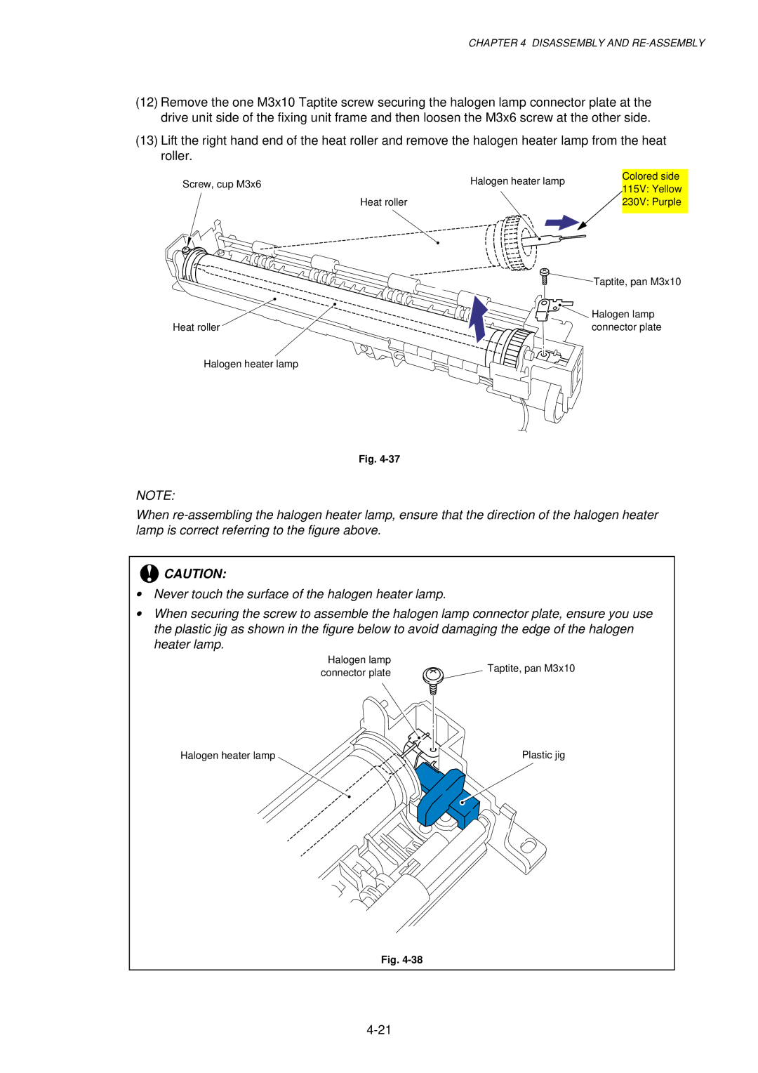
Halogen lamp Taptite, pan M3x10
Heat roller bearing Washer Heat roller gear
Heat roller gear Heat roller bearing Embossment
Heat roller cleaner Fixing unit frame Cleaner spring
Hooks Thermistor Fixing unit frame Taptite, cup M3x12
Fixing unit frame First eject roller Idle gear
PR2000057
26B
Base Plate
Ground wire Plastic chute Slit Main frame
Lower Tray Relay PCB Assy for HL-1250/1270N only
Main PCB Assy
Low-Voltage Power Supply PCB Assy
30A
PCB Assy
Engine PCB Assy / High-Voltage Power Supply PCB Assy
Toner sensor light
Solenoid Assy
Panel PCB Assy
Clutch lever spring For paper feed roller
Step Cassette guide L/F Taptite, cup M3x6
Fan Motor Assy
Toner Sensor PCB Assy Light Reception
Toner Sensor PCB Assy Light Emission
Paper Pick-up Roller Assy
Paper Feed Roller Assy
70a
Outer Chute
Packing
Consumable Parts
Replacement Procedure
Toner Cartridge
Periodic Maintenance
Assy
Periodical Replacement Parts
Cleaning the Printer Exterior
Periodical Cleaning
Cleaning the Drum Unit
Clean the Electrical Terminals
Cleaning the Scanner Window
Mtbf / Mttr
Periodic Maintenance
Initial Check
Introduction
Troubleshooting
Printer does not print Printed page has a problem
Identify the Problem
Operator Calls
Operator Calls & Service Calls
Service Calls
LED Indication Error Remedy
How the LEDs indicate an error
See ‘M-11 Service B’
Error Messages in the Status Monitor
Error Messages
Error Message Remedy
Error
RAM Error
NV-RAM Error
Main Motor Error
Error Message Printouts
Paper Loading Problems
Paper Problems
Problem Remedy
Clearing jammed paper
Paper Jams
Causes & countermeasures
Problem Type of Jam Cause Remedy
User Check
Paper Feeding Problems
Double feeding
Wrinkles or creases
Curl or Wave
Skew
Subsection 10.1 ‘Test Print
Software Setting Problems
Unable to print from application software under DOS
HL-1240/1250/1270N only
Value or alphabet following ‘BR’ is a product ID
PCB
No AC power supplied
No DC power supplied
Malfunctions
No paper supplied
Main motor does not rotate
Fixing heater temperature failure
Insufficient output from high-voltage power supply unit
BD failure
Fuser failure
Scanner failure
PCB 24V DC?
Engine interface error
ROM error / D-RAM error / NV-RAM error
PCI BUS error HL-1270N only
Image Defect Examples
Image Defects
Light
Troubleshooting Image Defect
Dark
Completely blank
All black
Dirt on the back of paper
How to clean the pressure roller
Black and blurred vertical streaks
Black vertical streaks in a gray background
Black and blurred horizontal stripes
White horizontal stripes
White vertical streaks
Poor fixing
Faulty registration
Faint print
Image distortion
White spots
Photosensitive drum
Black band
Black spots
Hollow print
Gray background
Horizontal lines
Downward fogging of solid black
Ghost
Light rain
Toner specks
Drum unit
Location of Grounding Contacts
Printer body & Paper cassette
Printer prints unexpectedly or it prints garbage
Incorrect Printout
For HL-1250/1270N only
User Check For DOS environment only
User Check For connecting by RS-232C/422A on HL-1250 only
Installation Problem
Network Problem for HL-1270N only
Intermittent Problem
Unix Troubleshooting
TCP/IP Troubleshooting
Windows 95/98 Peer to Peer Print LPR Troubleshooting
Windows NT/LAN Server TCP/IP Troubleshooting
Internet Print TCP/IP Troubleshooting
AppleTalk Troubleshooting
Novell Netware Troubleshooting
Apple TCP/IP Printing System 8.6 or later
Web Browser Troubleshooting TCP/IP
For the demo printer
Inspection Mode
Test Print Mode
Type of mode Function
Type of inspection
Inspection Mode
Ready
Factory inspection mode
Alarm
Drum
Troubleshooting
Troubleshooting
Biuk
Appendix 1. Serial NO. Descriptions
0 0 1 0
Appendix 2. Diameter / Circumference of Rollers
Media type setting All models
Appendix 3. Print Speeds with Various Settings
Media type setting HL-1240 demo model
Print Configuration for HL-1240/1250/1270N only
Appendix 4. HOW to Know Drum Unit Life & page Counter
Fig. A-2
Test Print for HL-1030 only
How to calculate drum unit life
How to Read the Drum Unit Life
How to Read the Page Counter
Fig. A-4
How to Read the Maintenance Information
Fig. A-7
Troubleshooting for Printer won’t print
Appendix 5. HOW to USE the SELF-DIAGNOSTICS Tools
Fig. A-10
Diagnostics
If you click the OK button in , the dialog box below appears
Fig. A-13
Printer Information
Items Descriptions
Appendix 6. Nvram Default Value
Fig. a
Appendix 7. Paper Cassette Information for Europe only
Appendix 8. Connection Diagram, HL-1030/1240
Appendix 9. Connection Diagram, HL-1250
Appendix 10. Connection Diagram, HL-1270N
Appendix 11. Main PCB Circuit Diagram, HL-1030/1240 1/2
Appendix 12. Main PCB Circuit Diagram, HL-1030/1240 2/2
Appendix 13. Main PCB Circuit Diagram, HL-1250/1270N 1/5
Appendix 14. Main PCB Circuit Diagram, HL-1250/1270N 2/5
Appendix 15. Main PCB Circuit Diagram, HL-1250/1270N 3/5
Appendix 16. Main PCB Circuit Diagram, HL-1250/1270N 4/5
Appendix 17. Main PCB Circuit Diagram, HL-1250/1270N 5/5
Appendix 18A. Engine PCB Circuit Diagram OLD
Appendix 18B. Engine PCB Circuit Diagram NEW
Appendix 19. Network Board Circuit Diagram, HL-1270N
Low-voltage PS Circuit 110
Low-voltage PS Circuit 220
High-voltage PS Circuit
CN1 CN2 DEV1
Electrode helical spring / Chute
High-voltage power supply PCB / Engine PCB
Index
Electrical terminal
22,4-30
2-10, 4-4, A-16
1-4
Index
PL-PRN001
Parts Reference List
B48K056 201A
REF.NO Code ’TY Description Symbol Remark
Contents
Solenoid Assy
REF.NO Code QTY Description Symbol Remark
Main Motor Assy
TAPTITE, CUP S M3X6
Frame / Drive Unit
Bearing
Joint
Conductor Bearing
Paper Feeder
Fixing UNIT, 115V SP
Cleaner Roller Assy
Cleaner Spring
REF.NO Code QTY Description Remark
Fixing Unit
Pressure Plate Spring
Paper Indicator
Paper Tray ASSY, LGL SP
Pressure Plate ASSY, LGL
Pressure Roller Holder
Paper Tray Assy 3 SP
Paper Tray ASSY, LEG SP
Paper Cassette
Model Plate
Rear Cover
TOP Cover
10 UL9142001 1 Second Eject Roller Assy
Covers
Main PCB ASSY, HL-1240 PB SP
Main PCB ASSY, HL-1030 SP
Main PCB ASSY, HL-1240 SP
Main PCB ASSY, HL-1240 HEB SP
HL-1030 HL-1240 HL-1250 HL-1270/1270N
LJ8330001 1 Protection Tube
Engine PCB Assy A, 1240 SP
Engine PCB Assy A, 1250 SP
LOW-VOLTAGE PS ASSY, 115V SP
Engine PCB
AC CORD, Chli
AC CORD, UL/CSA
AC Cord ASSY, SAA
AC Cord ASSY, SEV
High Voltage Power Supply PCB
Setup GUIDE, NOR
Setup GUIDE, FRA
Setup GUIDE, GER
Setup GUIDE, NL
Accessories
CARTON, HL-1240 US
Accessory Carton
CARTON, HL-1030 EU
CARTON, HL-1030 can
Packing Materials
Torx Screw Driver
Tool no Tool Name Remark
Molykote PG-662 ADD