Appendix A Troubleshooting
Reading the LEDs
Table |
| |||
|
|
|
|
|
LED |
| Color | State | Description |
|
|
|
| |
Appliance Status | Green | On | Standby or ready for operation | |
(location 2) |
|
|
|
|
| Green | Blinking | Degraded operation (for example, power | |
|
| |||
|
|
|
| supply nonredundancy, part of system |
|
|
|
| memory mapped out of BIOS) |
|
|
|
|
|
|
| Amber | On | One or more critical fault conditions |
|
|
|
|
|
|
| Amber | Blinking | One or more noncritical fault conditions |
|
|
|
| |
Hard Disk Drive | Green | On | HDD activity | |
(location 3) |
|
|
|
|
| Amber | On | HDD fault | |
|
| |||
|
|
|
| Note This is an aggregated indication for |
|
|
|
| all hard disk drives. Each hard disk |
|
|
|
| drive contains its own activity and |
|
|
|
| fault LEDs. |
|
|
|
| |
NICs (location 4) | Green | On | NIC activity | |
|
|
|
| |
System ID (location 5) | Blue |
| System identity | |
|
|
|
| Note LED can be toggled remotely or by |
|
|
|
| the |
|
|
|
| the system’s identity. |
|
|
|
|
|
NIC LEDs
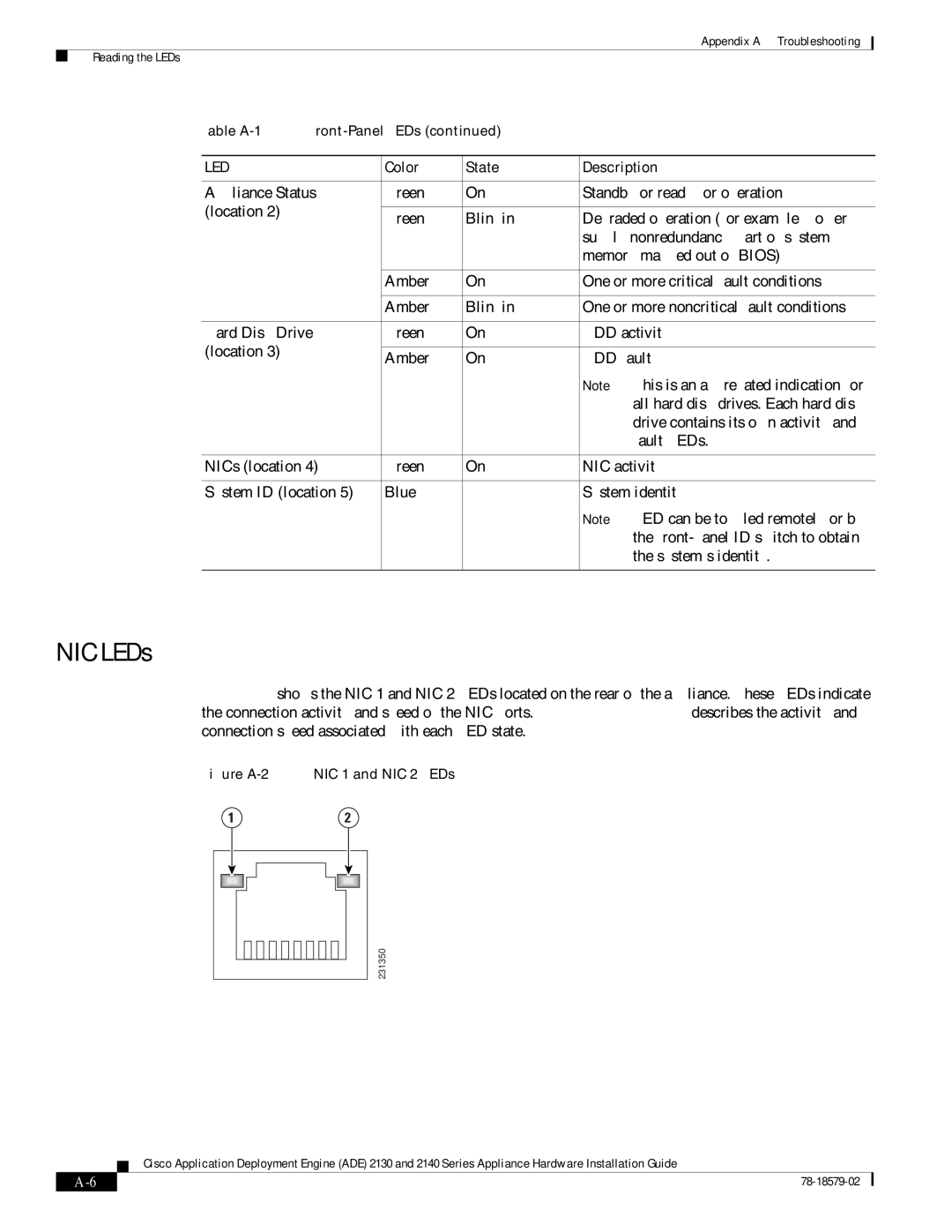
Figure A-2 shows the NIC 1 and NIC 2 LEDs located on the rear of the appliance. These LEDs indicate the connection activity and speed of the NIC ports. Table A-2 on page A-7 describes the activity and connection speed associated with each LED state.
Figure A-2 NIC 1 and NIC 2 LEDs
1 | 2 |
| 231350 |
Cisco Application Deployment Engine (ADE) 2130 and 2140 Series Appliance Hardware Installation Guide
|
| ||
|
|