Chapter 1 Introducing the Cisco Application Deployment Engine 2130 and 2140 Series Appliance
Hardware Features
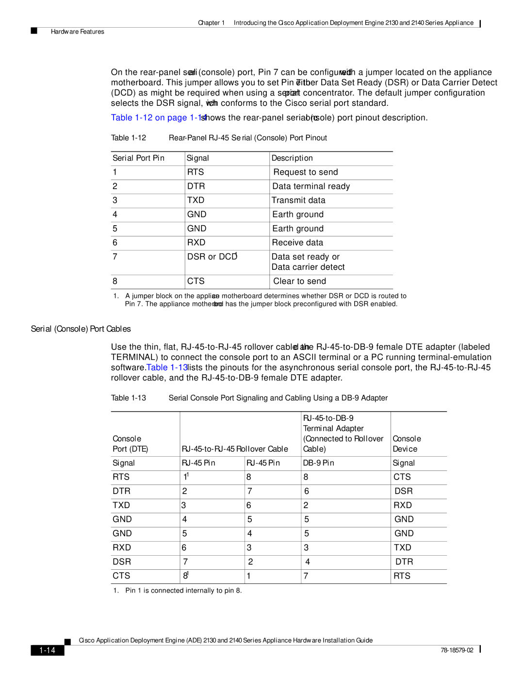
On the
Table
Table | |||
|
|
|
|
Serial Port Pin |
| Signal | Description |
|
|
|
|
1 |
| RTS | Request to send |
|
|
|
|
2 |
| DTR | Data terminal ready |
|
|
|
|
3 |
| TXD | Transmit data |
|
|
|
|
4 |
| GND | Earth ground |
|
|
|
|
5 |
| GND | Earth ground |
|
|
|
|
6 |
| RXD | Receive data |
|
|
|
|
7 |
| DSR or DCD1 | Data set ready or |
|
|
| Data carrier detect |
|
|
|
|
8 |
| CTS | Clear to send |
|
|
|
|
1.A jumper block on the appliance motherboard determines whether DSR or DCD is routed to Pin 7. The appliance motherboard has the jumper block preconfigured with DSR enabled.
Serial (Console) Port Cables
Use the thin, flat,
Table | Serial Console Port Signaling and Cabling Using a | ||||
|
|
|
|
|
|
|
|
|
|
|
|
|
|
|
| Terminal Adapter |
|
Console |
|
|
| (Connected to Rollover | Console |
Port (DTE) |
| Cable) | Device | ||
|
|
|
|
|
|
Signal |
| Signal | |||
|
|
|
|
|
|
RTS |
| 11 | 8 | 8 | CTS |
DTR |
| 2 | 7 | 6 | DSR |
|
|
|
|
|
|
TXD |
| 3 | 6 | 2 | RXD |
|
|
|
|
|
|
GND |
| 4 | 5 | 5 | GND |
|
|
|
|
|
|
GND |
| 5 | 4 | 5 | GND |
|
|
|
|
|
|
RXD |
| 6 | 3 | 3 | TXD |
|
|
|
|
|
|
DSR |
| 7 | 2 | 4 | DTR |
|
|
|
|
|
|
CTS |
| 81 | 1 | 7 | RTS |
1. Pin 1 is connected internally to pin 8.
Cisco Application Deployment Engine (ADE) 2130 and 2140 Series Appliance Hardware Installation Guide
| ||
|