Chapter 3 Installing the Cisco ADE 2130 and 2140 Series Appliance
Cisco ADE 2130 and 2140 Series Appliance Power
Warning Before performing any of the following procedures, ensure that power is removed from the DC circuit.
Statement 1003
Step 2 Turn off the DC power source at the circuit breaker, and tape the circuit breaker in the off position.
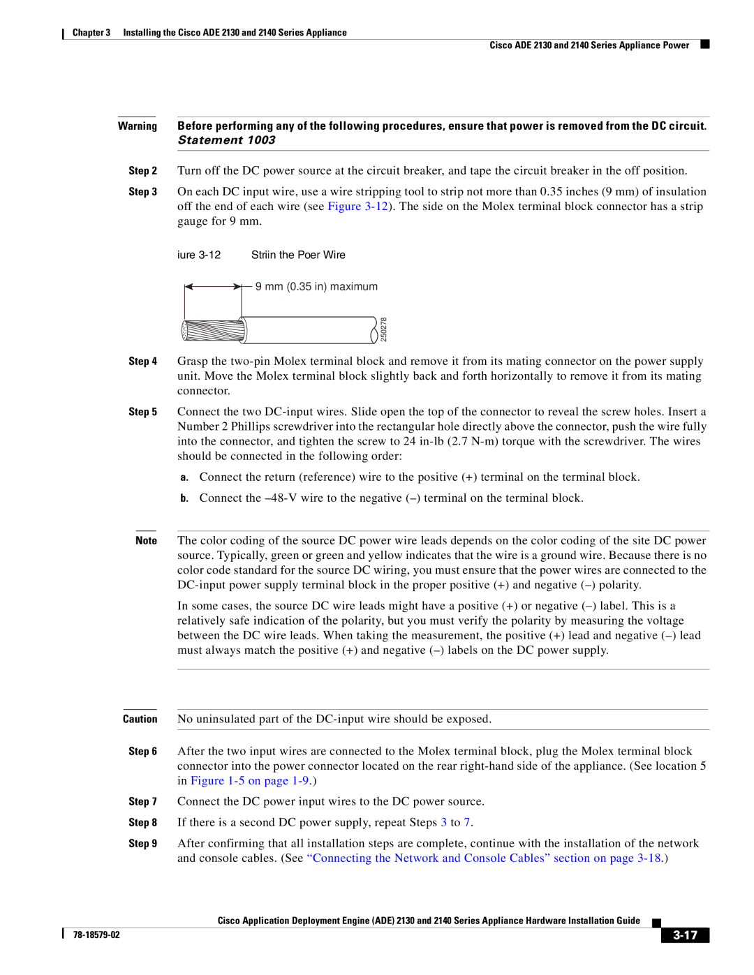
Step 3 On each DC input wire, use a wire stripping tool to strip not more than 0.35 inches (9 mm) of insulation off the end of each wire (see Figure
Figure 3-12 Stripping the Power Wire
9 mm (0.35 in) maximum
250278
Step 4 Grasp the
Step 5 Connect the two
a.Connect the return (reference) wire to the positive (+) terminal on the terminal block.
b.Connect the
Note The color coding of the source DC power wire leads depends on the color coding of the site DC power source. Typically, green or green and yellow indicates that the wire is a ground wire. Because there is no color code standard for the source DC wiring, you must ensure that the power wires are connected to the
In some cases, the source DC wire leads might have a positive (+) or negative
Caution No uninsulated part of the
Step 6 After the two input wires are connected to the Molex terminal block, plug the Molex terminal block connector into the power connector located on the rear
Step 7 Connect the DC power input wires to the DC power source.
Step 8 If there is a second DC power supply, repeat Steps 3 to 7.
Step 9 After confirming that all installation steps are complete, continue with the installation of the network and console cables. (See “Connecting the Network and Console Cables” section on page
Cisco Application Deployment Engine (ADE) 2130 and 2140 Series Appliance Hardware Installation Guide
|
|
| |
|
|