Supported DIMM Configuration
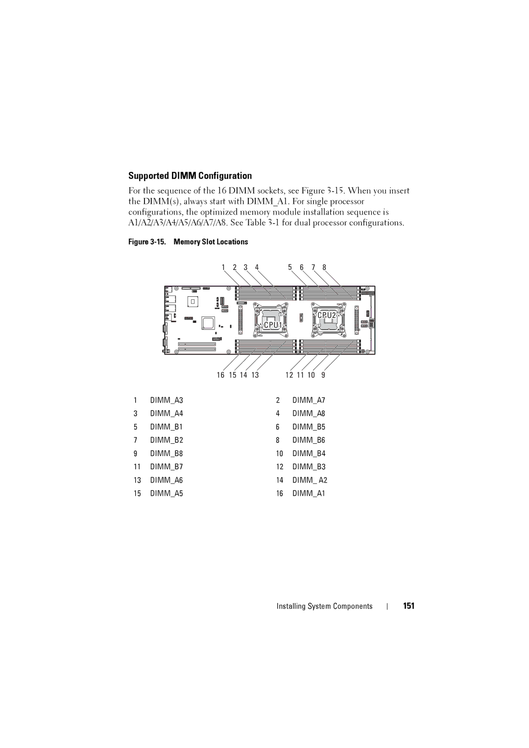
For the sequence of the 16 DIMM sockets, see Figure
Figure 3-15. Memory Slot Locations
1 | 2 |
|
| 3 | 4 | 5 |
| 6 | 7 | 8 |
|
|
|
|
|
|
| |||||||
|
|
|
|
|
|
|
|
|
|
|
|
|
|
|
|
|
|
|
|
|
|
|
|
|
|
|
|
|
|
|
|
|
|
|
|
|
|
|
|
|
|
|
|
|
|
|
|
|
|
|
|
|
|
|
|
|
|
|
|
|
|
|
|
|
|
|
|
|
|
|
|
|
|
|
|
|
|
|
|
|
|
|
|
|
|
|
|
|
|
|
|
|
|
|
|
|
|
|
|
|
|
|
|
|
|
|
|
|
|
|
|
|
|
|
|
|
|
|
|
|
|
|
|
|
CPU2 |
CPU1 |
| 16 | 15 14 | 13 |
| 12 | 11 10 | 9 |
1 | DIMM_A3 |
|
| 2 | DIMM_A7 | ||
3 | DIMM_A4 |
|
| 4 | DIMM_A8 | ||
5 | DIMM_B1 |
|
| 6 | DIMM_B5 | ||
7 | DIMM_B2 |
|
| 8 | DIMM_B6 | ||
9 | DIMM_B8 |
|
| 10 | DIMM_B4 | ||
11 | DIMM_B7 |
|
| 12 | DIMM_B3 | ||
13 | DIMM_A6 |
|
| 14 | DIMM_ A2 | ||
15 | DIMM_A5 |
|
| 16 | DIMM_A1 | ||
Installing System Components