5Disconnect the SAS, interface, and power cables from the back of the SAS backplane.
6Remove all expansion cards and the controller card. See "Removing an Expansion Card" on page 55.
7If present, disconnect and remove the RAC card.
8If present, remove the VRMs for processors 3 and 4. See "Removing a VRM" on page 67.
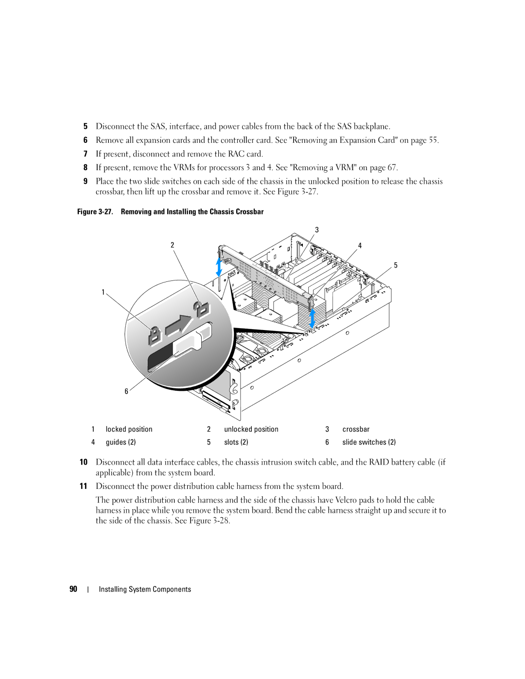
9Place the two slide switches on each side of the chassis in the unlocked position to release the chassis crossbar, then lift up the crossbar and remove it. See Figure
Figure 3-27. Removing and Installing the Chassis Crossbar
3
2 | 4 |
5
1
| 6 |
|
|
|
|
1 | locked position | 2 | unlocked position | 3 | crossbar |
4 | guides (2) | 5 | slots (2) | 6 | slide switches (2) |
10Disconnect all data interface cables, the chassis intrusion switch cable, and the RAID battery cable (if applicable) from the system board.
11Disconnect the power distribution cable harness from the system board.
The power distribution cable harness and the side of the chassis have Velcro pads to hold the cable harness in place while you remove the system board. Bend the cable harness straight up and secure it to the side of the chassis. See Figure
90