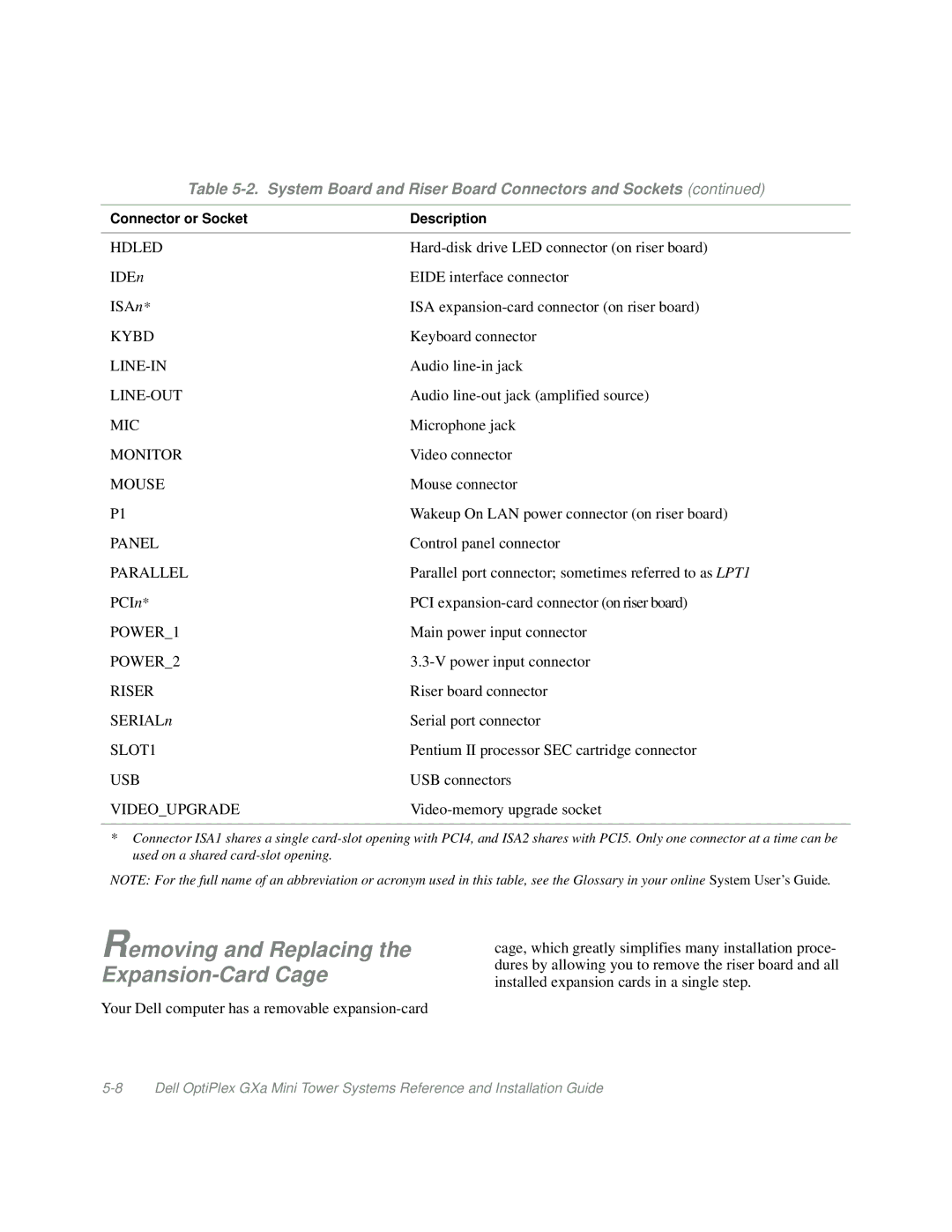
Table 5-2. System Board and Riser Board Connectors and Sockets (continued)
Connector or Socket | Description |
|
|
HDLED | |
IDEn | EIDE interface connector |
ISAn* | ISA |
KYBD | Keyboard connector |
Audio | |
Audio | |
MIC | Microphone jack |
MONITOR | Video connector |
MOUSE | Mouse connector |
P1 | Wakeup On LAN power connector (on riser board) |
PANEL | Control panel connector |
PARALLEL | Parallel port connector; sometimes referred to as LPT1 |
PCIn* | PCI |
POWER_1 | Main power input connector |
POWER_2 | |
RISER | Riser board connector |
SERIALn | Serial port connector |
SLOT1 | Pentium II processor SEC cartridge connector |
USB | USB connectors |
VIDEO_UPGRADE |
|
*Connector ISA1 shares a single
NOTE: For the full name of an abbreviation or acronym used in this table, see the Glossary in your online System User’s Guide.
Removing and Replacing the Expansion-Card Cage
Your Dell computer has a removable
cage, which greatly simplifies many installation proce- dures by allowing you to remove the riser board and all installed expansion cards in a single step.
