Chapter 6
Installing System Board Options
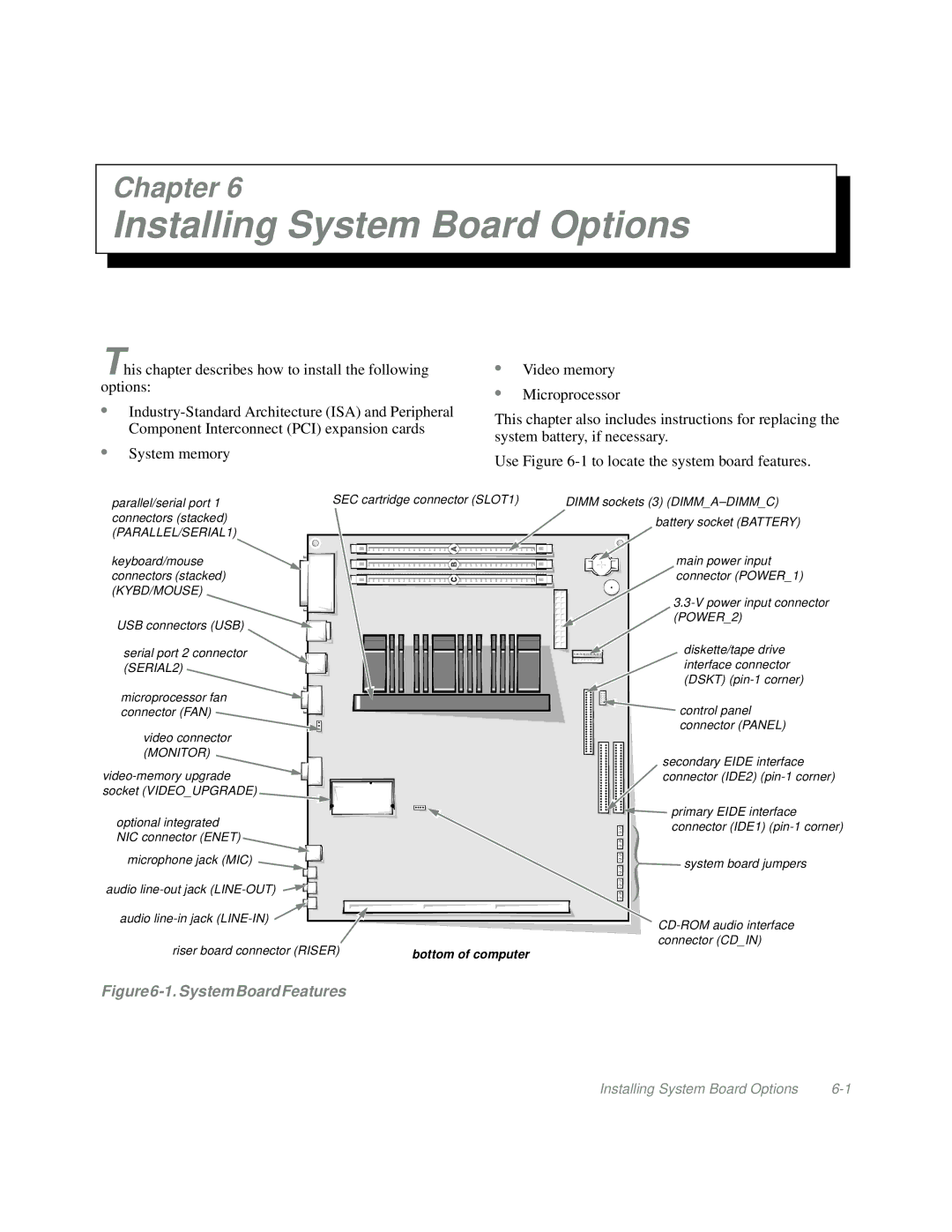
This chapter describes how to install the following options:
•
•System memory
•Video memory
•Microprocessor
This chapter also includes instructions for replacing the system battery, if necessary.
Use Figure
parallel/serial port 1 | SEC cartridge connector (SLOT1) |
| ||||
connectors (stacked) |
|
|
|
|
|
|
(PARALLEL/SERIAL1) |
|
|
|
|
|
|
|
|
|
|
|
|
|
|
|
|
|
|
|
|
|
|
|
|
|
|
|
|
|
|
|
|
|
|
keyboard/mouse connectors (stacked) (KYBD/MOUSE)
USB connectors (USB)
serial port 2 connector (SERIAL2)
microprocessor fan |
connector (FAN) |
video connector (MONITOR)
optional integrated
NIC connector (ENET) ![]() microphone jack (MIC)
microphone jack (MIC)
audio
audio ![]()
riser board connector (RISER) | bottom of computer |
DIMM sockets (3)
battery socket (BATTERY)
main power input connector (POWER_1)
diskette/tape drive interface connector (DSKT)
![]() control panel connector (PANEL)
control panel connector (PANEL)
secondary EIDE interface connector (IDE2)
![]()
![]()
![]()
![]() primary EIDE interface
primary EIDE interface ![]() connector (IDE1)
connector (IDE1)
![]() system board jumpers
system board jumpers
Figure6-1.SystemBoardFeatures
Installing System Board Options |