To upgrade the video memory, perform the following steps:
1.Remove the computer cover according to the instructions in “Removing the Computer Cover” in Chapter 5.
CAUTION: See “Protecting Against Electro- static Discharge” in the safety instructions at the front of this guide.
2.To access the
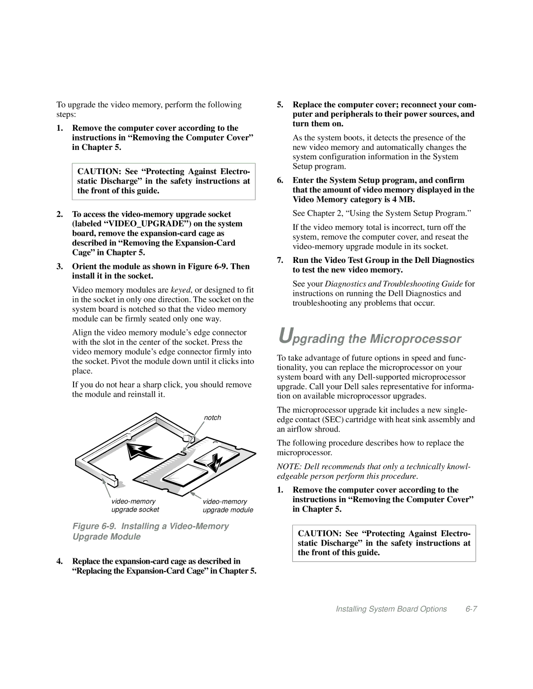
3.Orient the module as shown in Figure
Video memory modules are keyed, or designed to fit in the socket in only one direction. The socket on the system board is notched so that the video memory module can be firmly seated only one way.
Align the video memory module’s edge connector with the slot in the center of the socket. Press the video memory module’s edge connector firmly into the socket. Pivot the module down until it clicks into place.
If you do not hear a sharp click, you should remove the module and reinstall it.
notch
upgrade socket | upgrade module |
Figure 6-9. Installing a Video-Memory Upgrade Module
4.Replace the
5.Replace the computer cover; reconnect your com- puter and peripherals to their power sources, and turn them on.
As the system boots, it detects the presence of the new video memory and automatically changes the system configuration information in the System Setup program.
6.Enter the System Setup program, and confirm that the amount of video memory displayed in the Video Memory category is 4 MB.
See Chapter 2, “Using the System Setup Program.”
If the video memory total is incorrect, turn off the system, remove the computer cover, and reseat the
7.Run the Video Test Group in the Dell Diagnostics to test the new video memory.
See your Diagnostics and Troubleshooting Guide for instructions on running the Dell Diagnostics and troubleshooting any problems that occur.
Upgrading the Microprocessor
To take advantage of future options in speed and func- tionality, you can replace the microprocessor on your system board with any
The microprocessor upgrade kit includes a new single- edge contact (SEC) cartridge with heat sink assembly and an airflow shroud.
The following procedure describes how to replace the microprocessor.
NOTE: Dell recommends that only a technically knowl- edgeable person perform this procedure.
1.Remove the computer cover according to the instructions in “Removing the Computer Cover” in Chapter 5.
CAUTION: See “Protecting Against Electro- static Discharge” in the safety instructions at the front of this guide.
Installing System Board Options |