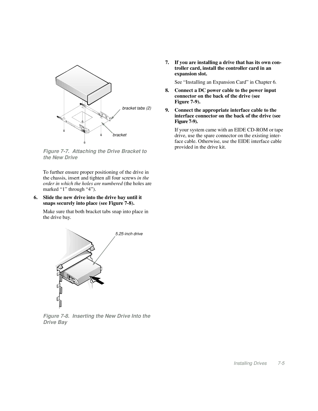
bracket tabs (2)
bracket
Figure 7-7. Attaching the Drive Bracket to the New Drive
To further ensure proper positioning of the drive in the chassis, insert and tighten all four screws in the order in which the holes are numbered (the holes are marked “1” through “4”).
6.Slide the new drive into the drive bay until it snaps securely into place (see Figure
Make sure that both bracket tabs snap into place in the drive bay.
Figure 7-8. Inserting the New Drive Into the Drive Bay
7.If you are installing a drive that has its own con- troller card, install the controller card in an expansion slot.
See “Installing an Expansion Card” in Chapter 6.
8.Connect a DC power cable to the power input connector on the back of the drive (see Figure
9.Connect the appropriate interface cable to the interface connector on the back of the drive (see Figure
If your system came with an EIDE
Installing Drives |