Table
.
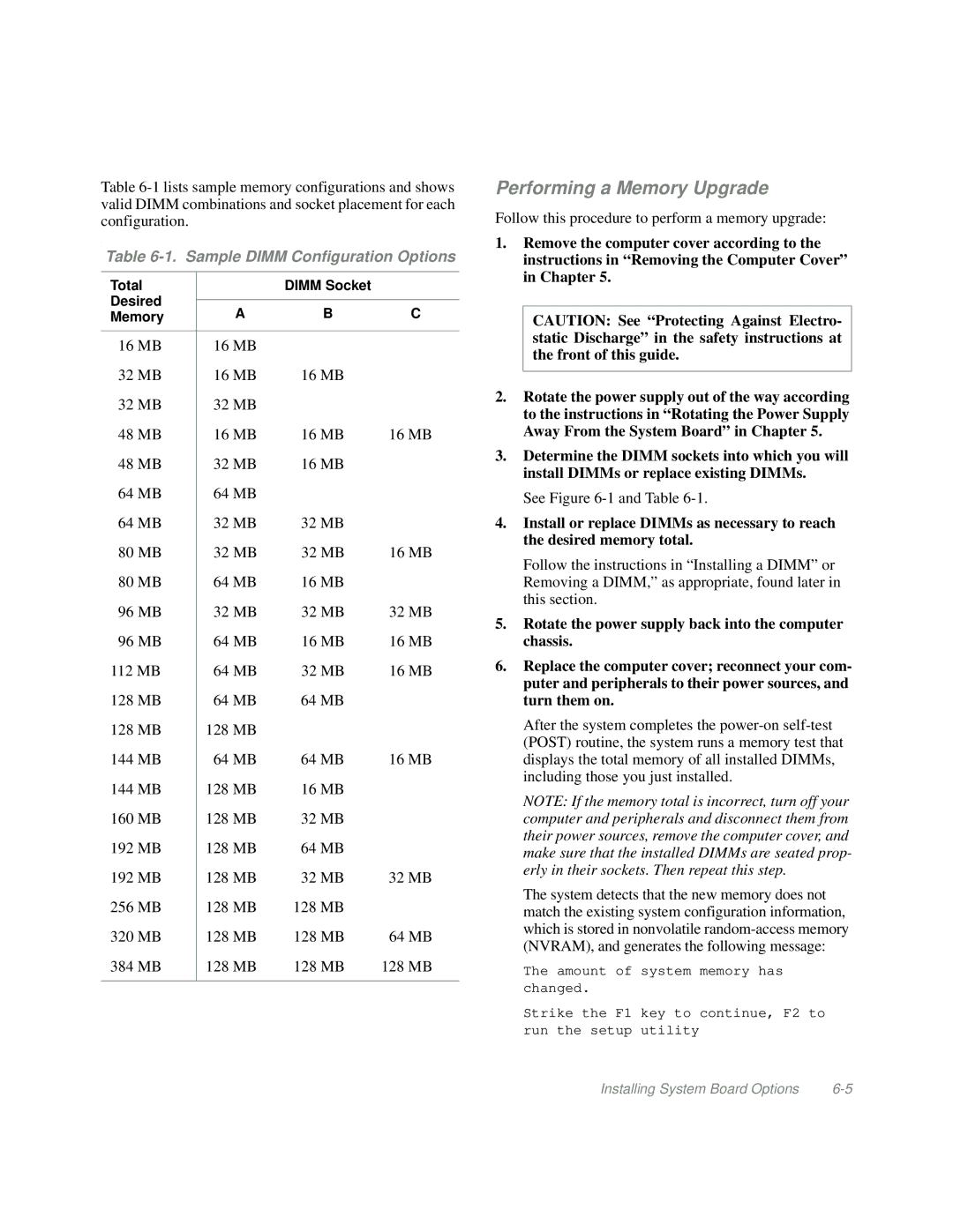
Table 6-1. Sample DIMM Configuration Options
Total |
| DIMM Socket |
| |
Desired |
|
|
| |
A | B | C | ||
Memory | ||||
|
|
|
| |
16 MB | 16 MB |
|
| |
32 MB | 16 MB | 16 MB |
| |
32 MB | 32 MB |
|
| |
48 MB | 16 MB | 16 MB | 16 MB | |
48 MB | 32 MB | 16 MB |
| |
64 MB | 64 MB |
|
| |
64 MB | 32 MB | 32 MB |
| |
80 MB | 32 MB | 32 MB | 16 MB | |
80 MB | 64 MB | 16 MB |
| |
96 MB | 32 MB | 32 MB | 32 MB | |
96 MB | 64 MB | 16 MB | 16 MB | |
112 MB | 64 MB | 32 MB | 16 MB | |
128 MB | 64 MB | 64 MB |
| |
128 MB | 128 MB |
|
| |
144 MB | 64 MB | 64 MB | 16 MB | |
144 MB | 128 MB | 16 MB |
| |
160 MB | 128 MB | 32 MB |
| |
192 MB | 128 MB | 64 MB |
| |
192 MB | 128 MB | 32 MB | 32 MB | |
256 MB | 128 MB | 128 MB |
| |
320 MB | 128 MB | 128 MB | 64 MB | |
384 MB | 128 MB | 128 MB | 128 MB | |
|
|
|
|
Performing a Memory Upgrade
Follow this procedure to perform a memory upgrade:
1.Remove the computer cover according to the instructions in “Removing the Computer Cover” in Chapter 5.
CAUTION: See “Protecting Against Electro- static Discharge” in the safety instructions at the front of this guide.
2.Rotate the power supply out of the way according to the instructions in “Rotating the Power Supply Away From the System Board” in Chapter 5.
3.Determine the DIMM sockets into which you will install DIMMs or replace existing DIMMs.
See Figure
4.Install or replace DIMMs as necessary to reach the desired memory total.
Follow the instructions in “Installing a DIMM” or Removing a DIMM,” as appropriate, found later in this section.
5.Rotate the power supply back into the computer chassis.
6.Replace the computer cover; reconnect your com- puter and peripherals to their power sources, and turn them on.
After the system completes the
NOTE: If the memory total is incorrect, turn off your computer and peripherals and disconnect them from their power sources, remove the computer cover, and make sure that the installed DIMMs are seated prop- erly in their sockets. Then repeat this step.
The system detects that the new memory does not match the existing system configuration information, which is stored in nonvolatile
The amount of system memory has changed.
Strike the F1 key to continue, F2 to run the setup utility
Installing System Board Options |