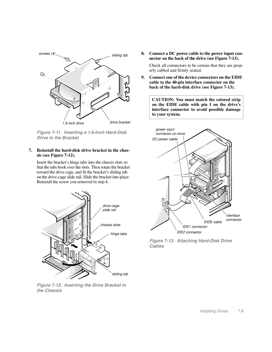
screws (4) | sliding tab |
|
drive bracket |
8.Connect a DC power cable to the power input con- nector on the back of the drive (see Figure
Check all connectors to be certain that they are prop- erly cabled and firmly seated.
9.Connect one of the device connectors on the EIDE cable to the
CAUTION: You must match the colored strip on the EIDE cable with pin 1 on the drive’s interface connector to avoid possible damage to your system.
Figure 7-11. Inserting a 1.6-Inch Hard-Disk Drive in the Bracket
7.Reinstall the
Insert the bracket’s hinge tabs into the chassis slots so that the tabs hook over the slots. Then rotate the bracket toward the drive cage, and fit the bracket’s sliding tab on the
chassis slots
hinge tabs
power input connector on drive
DC power cable
EIDE cable
![]()
![]() IDE1
IDE1![]()
![]()
![]() connector
connector
IDE2 connector
interface connector
sliding tab
Figure 7-12. Inserting the Drive Bracket in the Chassis
Figure 7-13. Attaching Hard-Disk Drive Cables
Installing Drives |