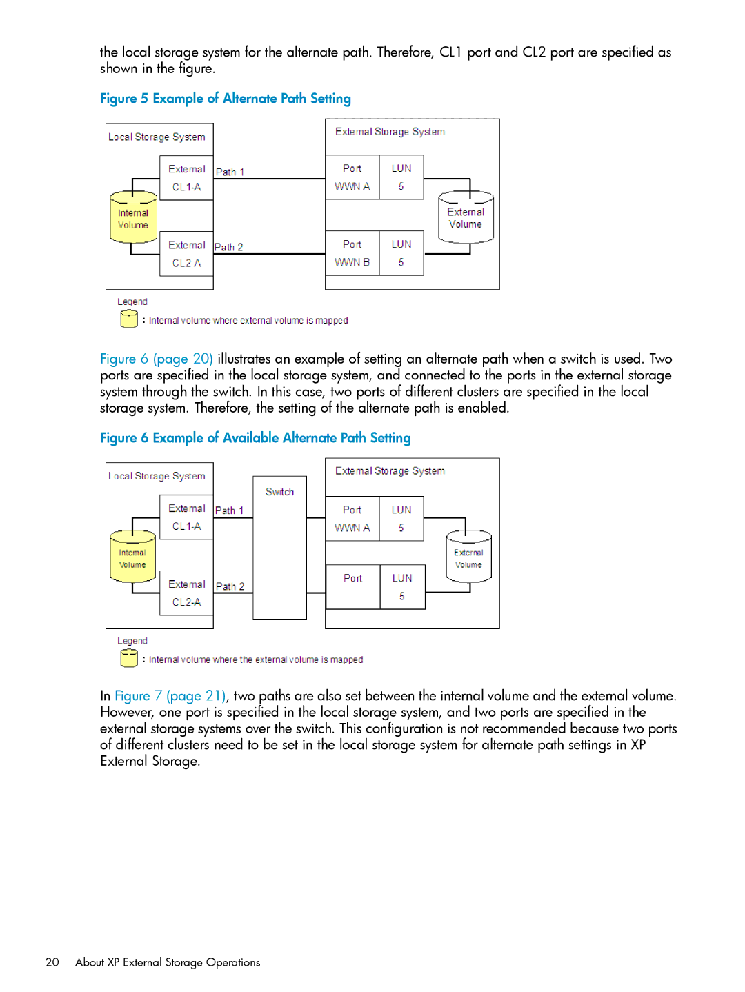
the local storage system for the alternate path. Therefore, CL1 port and CL2 port are specified as shown in the figure.
Figure 5 Example of Alternate Path Setting
Figure 6 (page 20) illustrates an example of setting an alternate path when a switch is used. Two ports are specified in the local storage system, and connected to the ports in the external storage system through the switch. In this case, two ports of different clusters are specified in the local storage system. Therefore, the setting of the alternate path is enabled.
Figure 6 Example of Available Alternate Path Setting
In Figure 7 (page 21), two paths are also set between the internal volume and the external volume. However, one port is specified in the local storage system, and two ports are specified in the external storage systems over the switch. This configuration is not recommended because two ports of different clusters need to be set in the local storage system for alternate path settings in XP External Storage.