10 Attach the fan cable by pressing firmly down until it clicks into
11Position the power supply | cable connector | so that the |
| side | of | |||||||||
| with | the tabs faces the retaining clips. Then, | press | firmly | down | |||||||||
| into | place. |
|
|
|
|
|
|
|
|
|
|
| |
12 Reinstall the | cover. See | “Reinstalling | the | Cover” | on | page | for | |||||||
| instructions. |
|
|
|
|
|
|
|
|
|
|
| ||
| Note: | The customer must reload operational code | and | configuration | ||||||||||
| mation | after | the | system | board | is | replaced. |
|
|
|
|
| ||
|
|
|
|
|
|
|
|
|
|
|
|
| ||
Single | (SIMM) |
|
|
|
|
|
|
|
|
|
|
| ||
Refer to “Handling | ||||||||||||||
installing | a | SIMM. |
|
|
|
|
|
|
|
|
|
|
| |
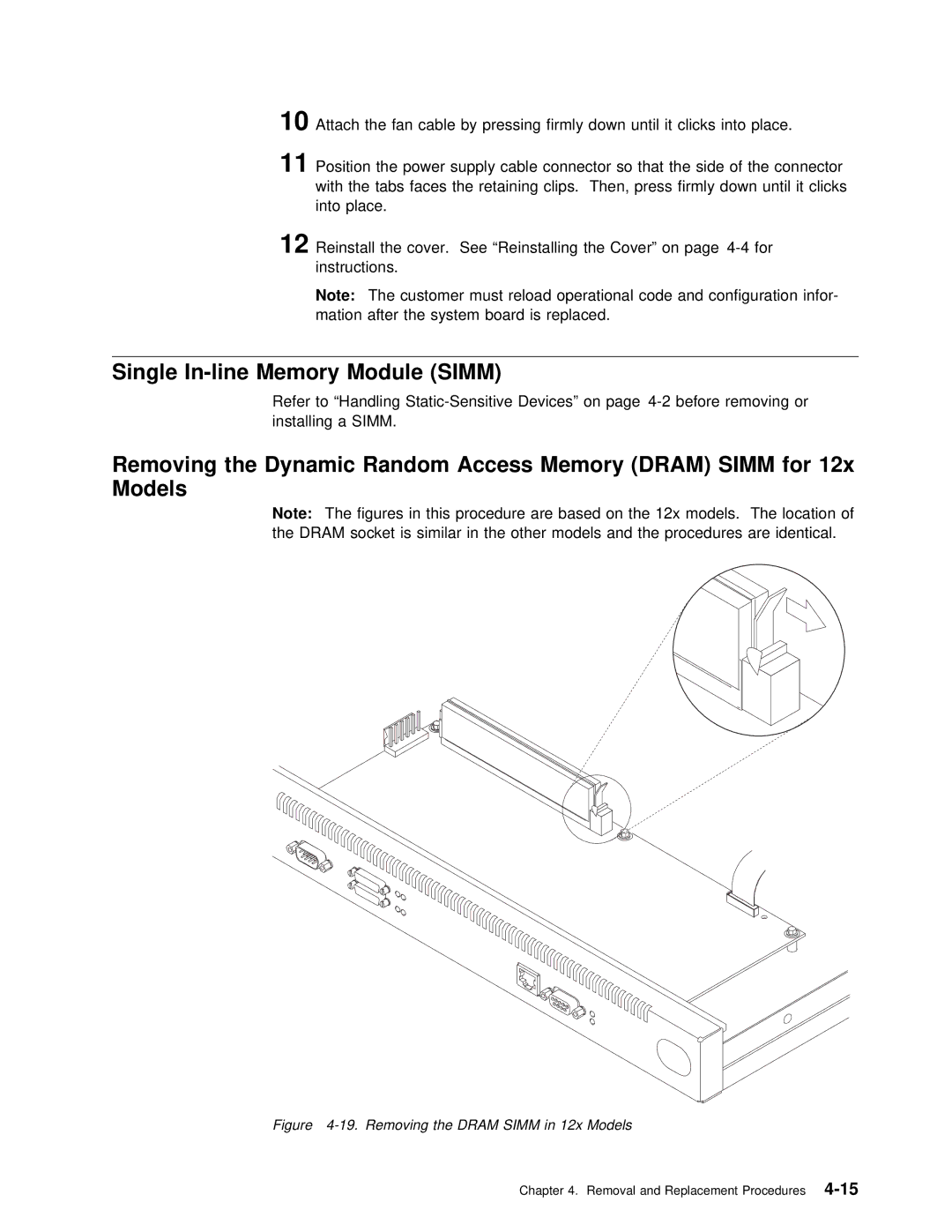
Removing the Dynamic | Random | Access | Memory | (DRAM) | SIMM | for | 12x |
|
|
|
|
|
| |
Models |
|
|
|
|
|
|
|
|
|
|
|
|
|
|
Note: | The | figures in this procedure are based on | the | 12x models. T | ||||||||||
the | DRAM | socket is similar in | the | other | models and | the | procedures a | |||||||
Figure 4-19. Removing the DRAM SIMM in 12x Models
Chapter 4. Removal and Replacement