Also | make | sure | that | the | connectors | feed through the space | betw |
and | rear | of | the cover and the connectors without the jumpers a | ||||
to | the power | supplies. |
|
|
| ||
5 Replace | the | screws | that | attach | the power supply cover to | the | |
shown in | Figure | on page |
|
| |||
6 If the Adapter Enablement Feature is installed, position the conne adapter riser card so that the side of the connector with th retaining clips. Then, press firmly down until it clicks into place. firmly seated.
7 | Position the connector to | the system | board so | that the side of | ||||||||
| with the tabs faces the | retaining | clips. Then, | press | firmly | down | ||||||
| into place. Be sure it | is | firmly | seated. |
|
|
| |||||
8 | If | the | Adapter | Enablement | Feature | is | installed, | connect | the | jumpe | ||
| the | base | power | supply | and | the | adapter power | supply | together. | |||
Fan
Note: | For the 14T and | 24x models, removing | the | power | supply | cover | wi | ||||
fan removal process. Instructions on removing and | replacing | the | power | s | |||||||
cover | are contained in | “Removing | the | Base | Power | Supply | for | 14T and | 2 | ||
on page | Power | Supply for | 14T | and | 24x | Models” | |||||
page |
|
|
|
|
|
|
|
|
|
| |
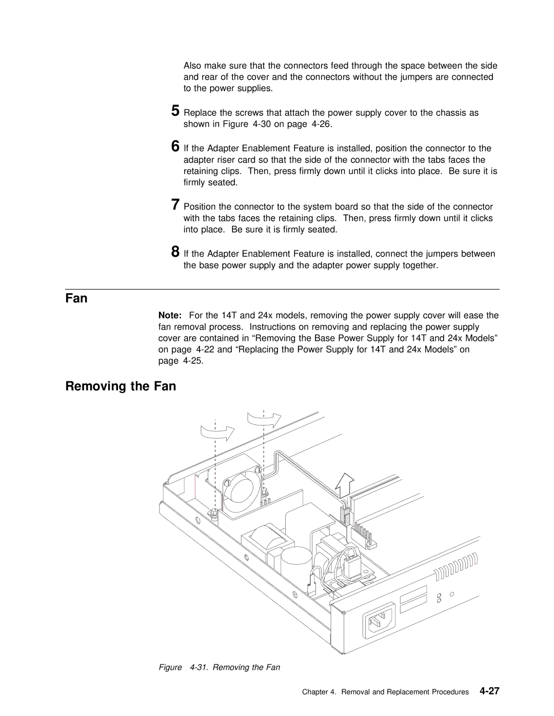
Removing the Fan
Figure 4-31. Removing the Fan
Chapter 4. Removal and Replacement