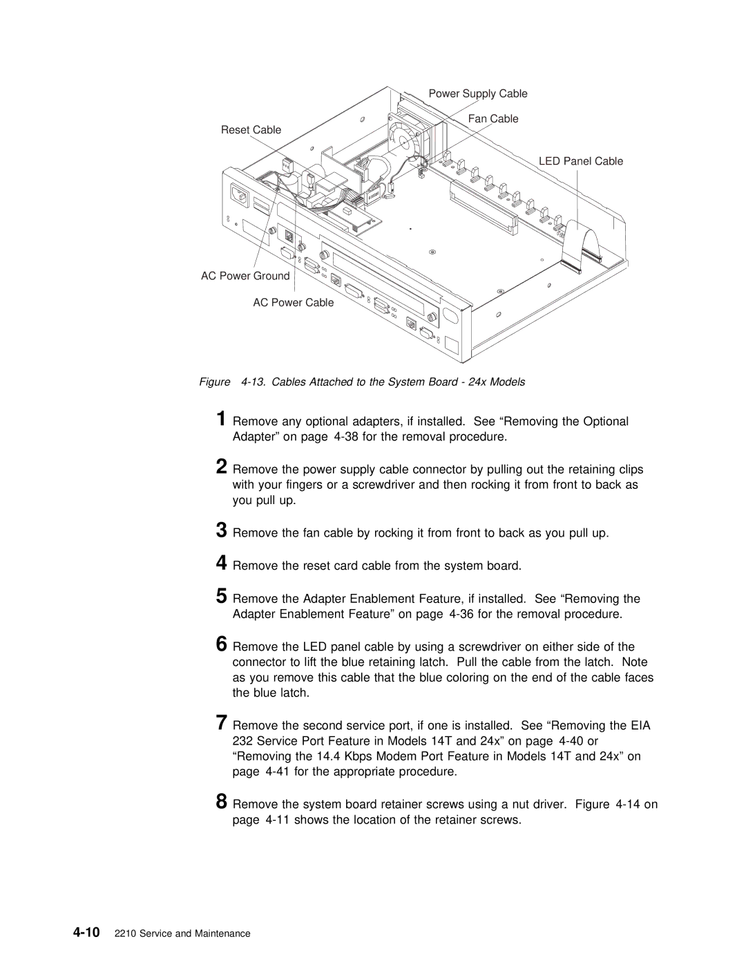
Power Supply Cable
Fan Cable
Reset Cable
LED Panel Cable
AC Power Ground
AC Power Cable
Figure 4-13. Cables Attached to the System Board - 24x Models
1Remove any optional adapters, if installed. See “Removing the Optiona Adapter” on page
2 | Remove | the |
| power | supply | cable |
| connector | by | pulling | out the | retaini | |||||||||||||
| with | your | fingers |
| or | a | screwdriver | and | then | rocking | it | from | front | ||||||||||||
| you | pull | up. |
|
|
|
|
|
|
|
|
|
|
|
|
|
|
|
|
|
|
|
| ||
3 | Remove | the |
| fan cable by rocking it from front | to | back | as | you | pu | ||||||||||||||||
4 | Remove | the |
| reset card cable from the system board. |
|
|
| ||||||||||||||||||
5 | Remove | the |
| Adapter Enablement Feature, if installed. See “Removing th | |||||||||||||||||||||
| Adapter |
| Enablement | Feature” | on | page | the | removal | procedure. | ||||||||||||||||
6 | Remove | the |
| LED | panel cable by using a screwdriver on either side | ||||||||||||||||||||
| connector | to | lift | the | blue | retaining | latch. Pull | the cable from | the | ||||||||||||||||
| as | you |
| remove | this | cable | that | the | blue | coloring | on | the | end of t | ||||||||||||
| the | blue | latch. |
|
|
|
|
|
|
|
|
|
|
|
|
|
|
|
|
|
| ||||
7 | Remove | the |
| second |
| service port, if one is installed. See “Removing | |||||||||||||||||||
| 232 | Service | Port | Feature in Models 14T and 24x” on page | |||||||||||||||||||||
| “Removing |
| the | 14.4 | Kbps | Modem | Port | Feature | in | Models | 14T | and | 24x” | ||||||||||||
| page | for | the | appropriate |
| procedure. |
|
|
|
|
|
|
|
| |||||||||||
8 | Remove | the |
| system |
| board | retainer | screws | using |
| a | nut | driver. Figure | ||||||||||||
| page | shows | the | location of | the | retainer | screws. |
|
|
| |||||||||||||||