8 Attach | the | fan cable | by | pressing firmly down until it | clicks | into |
9 Position | the | power supply | cable connector so that the | side | of | |
with the tabs faces | the | retaining clips. Then, press | firmly | down | ||
into place. |
|
|
|
|
| |
10 Reinstall the cover. See “Reinstalling the Cover” on page
Note: The customer must reload operational code and configuration mation after the system board is replaced.
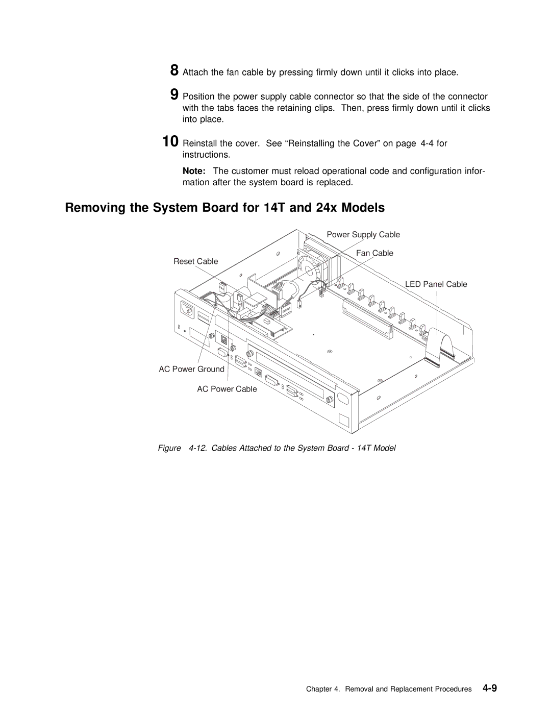
Removing the System Board for 14T and 24x Models
Power Supply Cable
Fan Cable
Reset Cable
LED Panel Cable
AC Power Ground
AC Power Cable
Figure 4-12. Cables Attached to the System Board - 14T Model
Chapter 4. Removal and Replacement