SEAT FRAME | SECTION 6 |
|
|
ASBA (FIGURE 3)
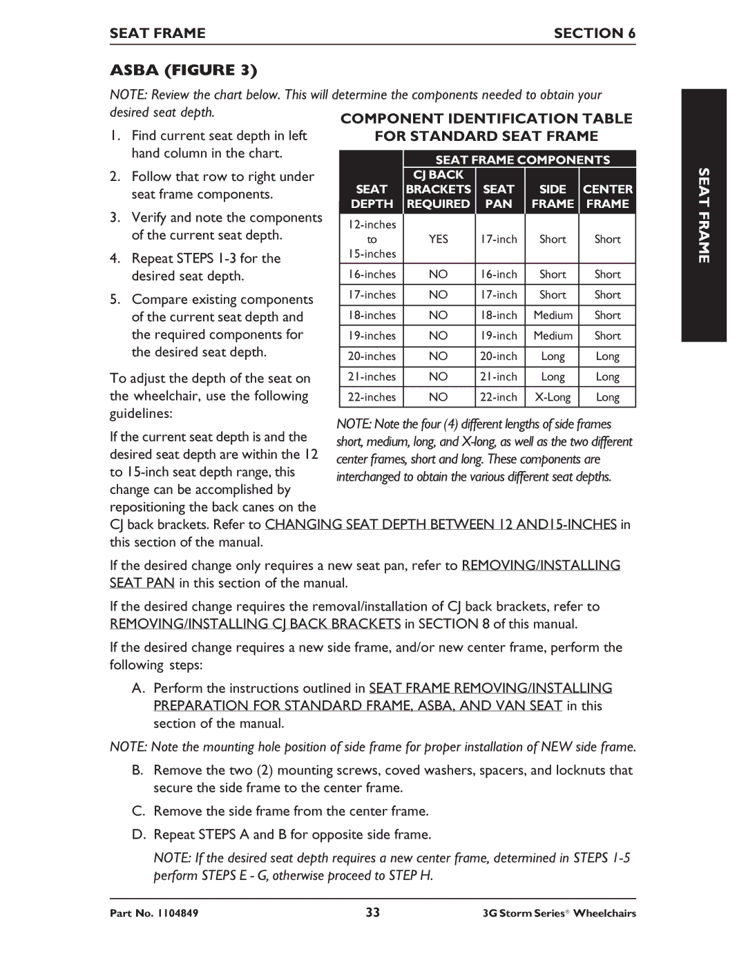
NOTE: Review the chart below. This will determine the components needed to obtain your desired seat depth.
1.Find current seat depth in left hand column in the chart.
2.Follow that row to right under seat frame components.
3.Verify and note the components of the current seat depth.
4.Repeat STEPS 1-3 for the desired seat depth.
5.Compare existing components of the current seat depth and the required components for the desired seat depth.
To adjust the depth of the seat on the wheelchair, use the following guidelines:
| SEAT FRAME COMPONENTS | ||||
| CJ BACK |
|
|
| |
SEAT | BRACKETS | SEAT | SIDE | CENTER | |
DEPTH | REQUIRED | PAN | FRAME | FRAME | |
|
|
|
|
| |
|
|
|
| ||
to | YES | Short | Short | ||
|
|
|
| ||
|
|
|
|
| |
NO | Short | Short | |||
|
|
|
|
| |
NO | Short | Short | |||
|
|
|
|
| |
NO | Medium | Short | |||
|
|
|
|
| |
NO | Medium | Short | |||
|
|
|
|
| |
NO | Long | Long | |||
|
|
|
|
| |
NO | Long | Long | |||
|
|
|
|
| |
NO | Long | ||||
|
|
|
|
| |
SEAT FRAME
If the current seat depth is and the desired seat depth are within the 12 to
CJ back brackets. Refer to CHANGING SEAT DEPTH BETWEEN 12
If the desired change only requires a new seat pan, refer to REMOVING/INSTALLING SEAT PAN in this section of the manual.
If the desired change requires the removal/installation of CJ back brackets, refer to REMOVING/INSTALLING CJ BACK BRACKETS in SECTION 8 of this manual.
If the desired change requires a new side frame, and/or new center frame, perform the following steps:
A.Perform the instructions outlined in SEAT FRAME REMOVING/INSTALLING PREPARATION FOR STANDARD FRAME, ASBA, AND VAN SEAT in this section of the manual.
NOTE: Note the mounting hole position of side frame for proper installation of NEW side frame.
B.Remove the two (2) mounting screws, coved washers, spacers, and locknuts that secure the side frame to the center frame.
C.Remove the side frame from the center frame.
D.Repeat STEPS A and B for opposite side frame.
NOTE: If the desired seat depth requires a new center frame, determined in STEPS
Part No. 1104849 | 33 | 3G Storm Series® Wheelchairs |
