WHEELS/MOTORS
SECTION 12 | WHEELS/MOTORS |
|
|
REMOVING
1.Remove the battery boxes. Refer to REMOVING/INSTALLING BATTERY BOXES in SECTION 9 of this manual.
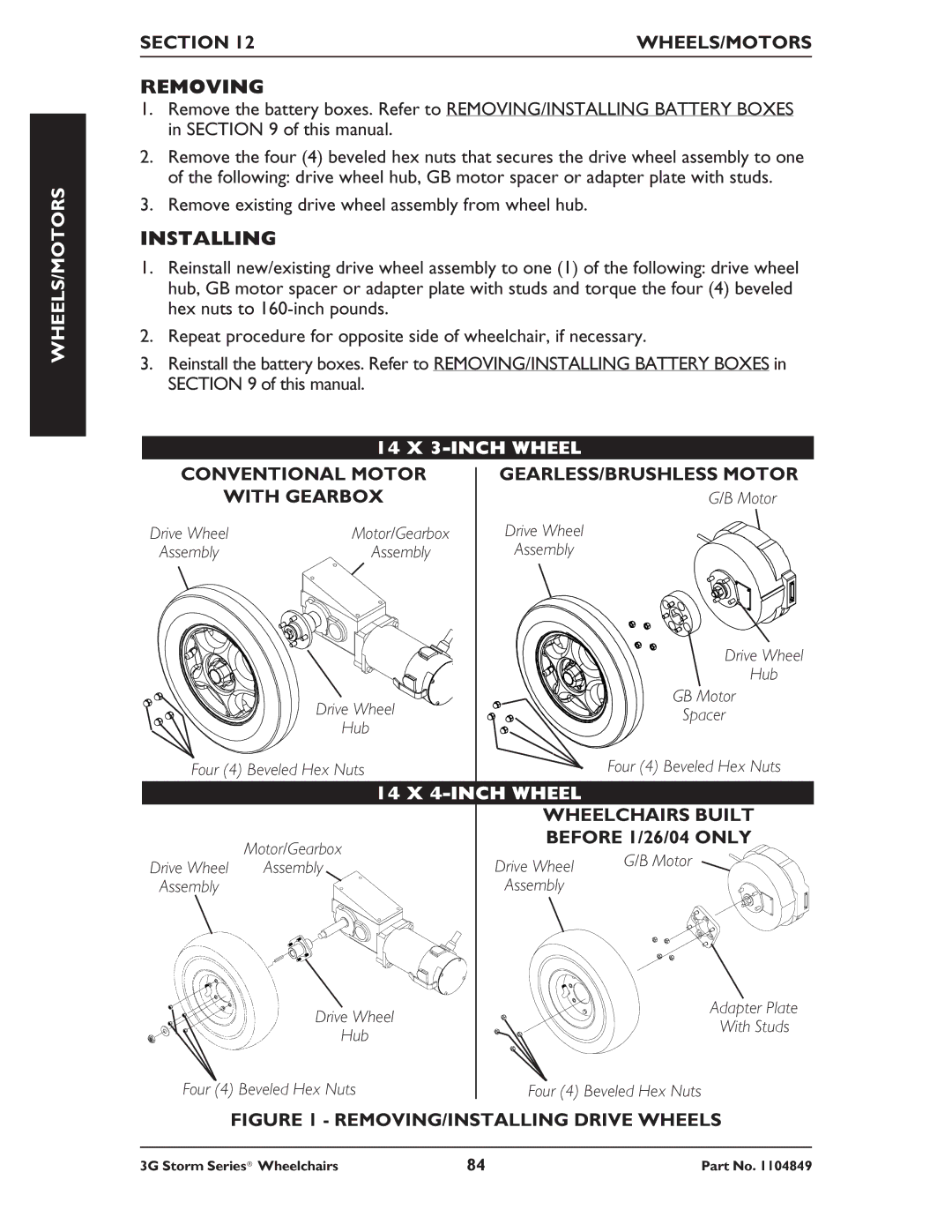
2.Remove the four (4) beveled hex nuts that secures the drive wheel assembly to one of the following: drive wheel hub, GB motor spacer or adapter plate with studs.
3.Remove existing drive wheel assembly from wheel hub.
INSTALLING
1.Reinstall new/existing drive wheel assembly to one (1) of the following: drive wheel hub, GB motor spacer or adapter plate with studs and torque the four (4) beveled hex nuts to
2.Repeat procedure for opposite side of wheelchair, if necessary.
3.Reinstall the battery boxes. Refer to REMOVING/INSTALLING BATTERY BOXES in SECTION 9 of this manual.
| 14 X | |
CONVENTIONAL MOTOR | GEARLESS/BRUSHLESS MOTOR | |
WITH GEARBOX | G/B Motor | |
Drive Wheel | Motor/Gearbox | Drive Wheel |
Assembly | Assembly | Assembly |
|
| Drive Wheel |
|
| Hub |
| Drive Wheel | GB Motor |
| Spacer | |
| Hub | |
|
| |
Four (4) Beveled Hex Nuts | Four (4) Beveled Hex Nuts | |
14 X 4-INCH WHEEL WHEELCHAIRS BUILT
Motor/Gearbox | BEFORE 1/26/04 ONLY | ||
| G/B Motor | ||
Drive Wheel Assembly | Drive Wheel | ||
| |||
Assembly | Assembly |
| |
Drive Wheel | Adapter Plate | |
With Studs | ||
Hub | ||
| ||
Four (4) Beveled Hex Nuts | Four (4) Beveled Hex Nuts |
FIGURE 1 - REMOVING/INSTALLING DRIVE WHEELS
3G Storm Series® Wheelchairs | 84 | Part No. 1104849 |
