WHEELS/MOTORS | SECTION 12 |
|
|
B.Secure new/existing rim and new/existing tire with flat free to gearless/brushless motor with the three (3) M8 x
NOTE: Once all three (3) mounting screws are in place, install one (1) shorter mounting screw in each of the two (2) remaining mounting holes. Remove one (1) longer mounting screw at a time and replace with the existing M8 x
2.Reinstall battery boxes. Refer to REMOVING/INSTALLING BATTERY BOXES in SECTION 9 of this manual.
3.If wheelchair is equipped with pneumatic tires, inflate tire to proper tire pressure located on the side wall of the tire.
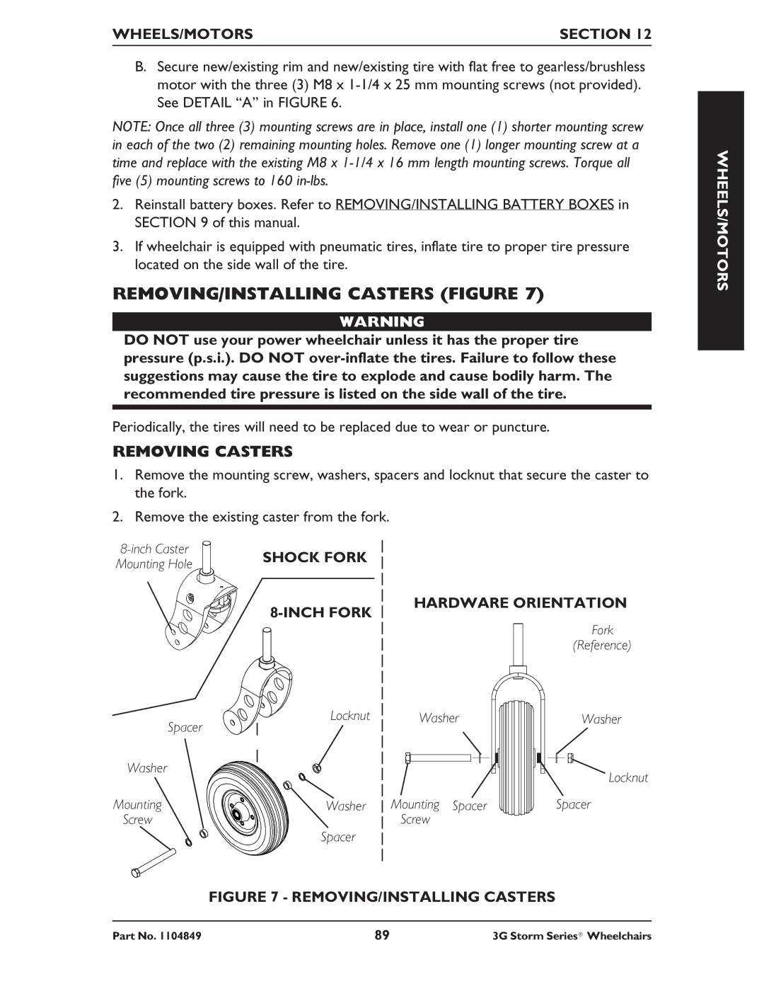
REMOVING/INSTALLING CASTERS (FIGURE 7)
WARNING
DO NOT use your power wheelchair unless it has the proper tire pressure (p.s.i.). DO NOT
Periodically, the tires will need to be replaced due to wear or puncture.
REMOVING CASTERS
1.Remove the mounting screw, washers, spacers and locknut that secure the caster to the fork.
2.Remove the existing caster from the fork.
SHOCK FORK | ||
Mounting Hole | ||
|
|
| HARDWARE ORIENTATION | |
|
|
| |
|
|
| Fork |
|
|
| (Reference) |
| Locknut | Washer | Washer |
| Spacer |
|
|
Washer |
|
| Locknut |
|
|
| |
Mounting | Washer | Mounting Spacer | Spacer |
Screw |
| Screw |
|
| Spacer |
|
|
| FIGURE 7 - REMOVING/INSTALLING CASTERS |
| |
WHEELS/MOTORS
Part No. 1104849 | 89 | 3G Storm Series® Wheelchairs |
