SEAT FRAME | SECTION 6 |
|
|
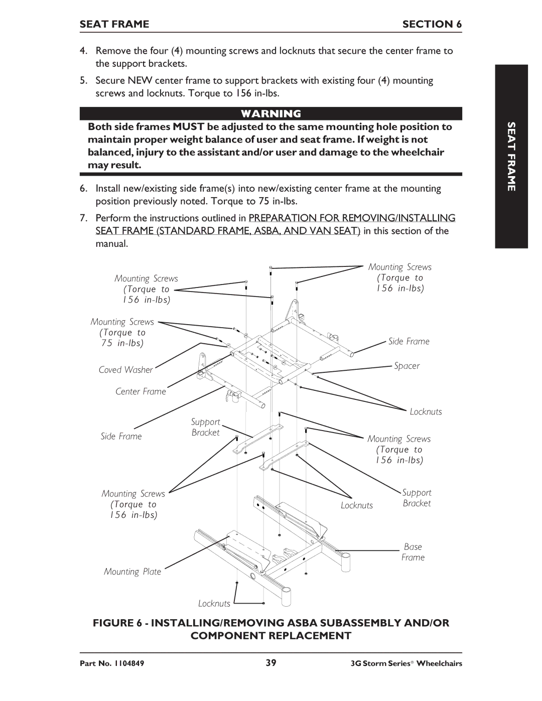
4.Remove the four (4) mounting screws and locknuts that secure the center frame to the support brackets.
5.Secure NEW center frame to support brackets with existing four (4) mounting screws and locknuts. Torque to 156
WARNING
Both side frames MUST be adjusted to the same mounting hole position to maintain proper weight balance of user and seat frame. If weight is not balanced, injury to the assistant and/or user and damage to the wheelchair may result.
6.Install new/existing side frame(s) into new/existing center frame at the mounting position previously noted. Torque to 75
7.Perform the instructions outlined in PREPARATION FOR REMOVING/INSTALLING SEAT FRAME (STANDARD FRAME, ASBA, AND VAN SEAT) in this section of the manual.
| Mounting Screws | ||
Mounting Screws | (Torque to | ||
(Torque to | 156 | ||
156 |
|
| |
Mounting Screws |
|
| |
(Torque to | Side Frame | ||
75 | |||
Coved Washer |
| Spacer | |
|
| ||
Center Frame |
|
| |
|
| Locknuts | |
| Support |
| |
Side Frame | Bracket |
| |
Mounting Screws | |||
| |||
| (Torque to | ||
| 156 | ||
Mounting Screws |
| Support | |
(Torque to | Locknuts | Bracket | |
156 |
|
| |
|
| Base | |
|
| Frame | |
Mounting Plate |
|
| |
Locknuts
FIGURE 6 - INSTALLING/REMOVING ASBA SUBASSEMBLY AND/OR
COMPONENT REPLACEMENT
SEAT FRAME
Part No. 1104849 | 39 | 3G Storm Series® Wheelchairs |
