Note: The amount of usable memory is reduced depending on the system configuration. A certain amount of memory must be reserved for system resources. To view the total amount of installed memory and the amount of configured memory, run the Setup Utility. For additional information, see “Using the Setup Utility” on page 138.
vA minimum of one DIMM must be installed for each microprocessor. For example, you must install a minimum of two DIMMs if the server has two microprocessors installed. However, to improve system performance, install a minimum of three DIMMs for each microprocessor.
vThe maximum operating speed of the server is determined by the slowest DIMM install in the server.
vThe server comes with a minimum of two 1 GB DIMMs, installed in slots 3 and 6.
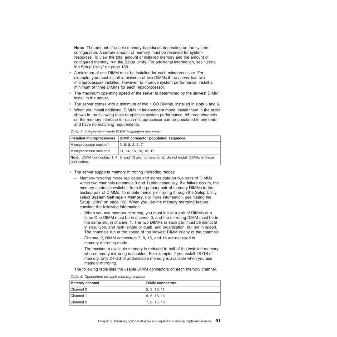
vWhen you install additional DIMMs in independent mode, install them in the order shown in the following table to optimize system performance. All three channels on the memory interface for each microprocessor can be populated in any order and have no matching requirements.
Table 7. Independent mode DIMM installation sequence
Installed microprocessors | DIMM connector population sequence |
|
|
Microprocessor socket 1 | 3, 6, 8, 2, 5, 7 |
|
|
Microprocessor socket 2 | 11, 14, 16, 10, 13, 15 |
|
|
Note: DIMM connectors 1, 4, 9, and 12 are not functional. Do not install DIMMs in these connectors.
vThe server supports memory mirroring (mirroring mode):
–
-When you use memory mirroring, you must install a pair of DIMMs at a time. One DIMM must be in channel 0, and the mirroring DIMM must be in the same slot in channel 1. The two DIMMs in each pair must be identical in size, type, and rank (single or dual), and organization, but not in speed. The channels run at the speed of the slowest DIMM in any of the channels.
-Channel 2, DIMM connectors 7, 8, 15, and 16 are not used in
-The maximum available memory is reduced to half of the installed memory when memory mirroring is enabled. For example, if you install 48 GB of memory, only 24 GB of addressable memory is available when you use memory mirroring.
The following table lists the usable DIMM connectors on each memory channel.
Table 8. Connectors on each memory channel
Memory channel | DIMM connectors |
|
|
Channel 0 | 2, 3, 10, 11 |
|
|
Channel 1 | 5, 6, 13, 14 |
|
|
Channel 2 | 7, 8, 15, 16 |
|
|
Chapter 5. Installing optional devices and replacing customer replaceable units 91