7 |
Connector Pin Assignments
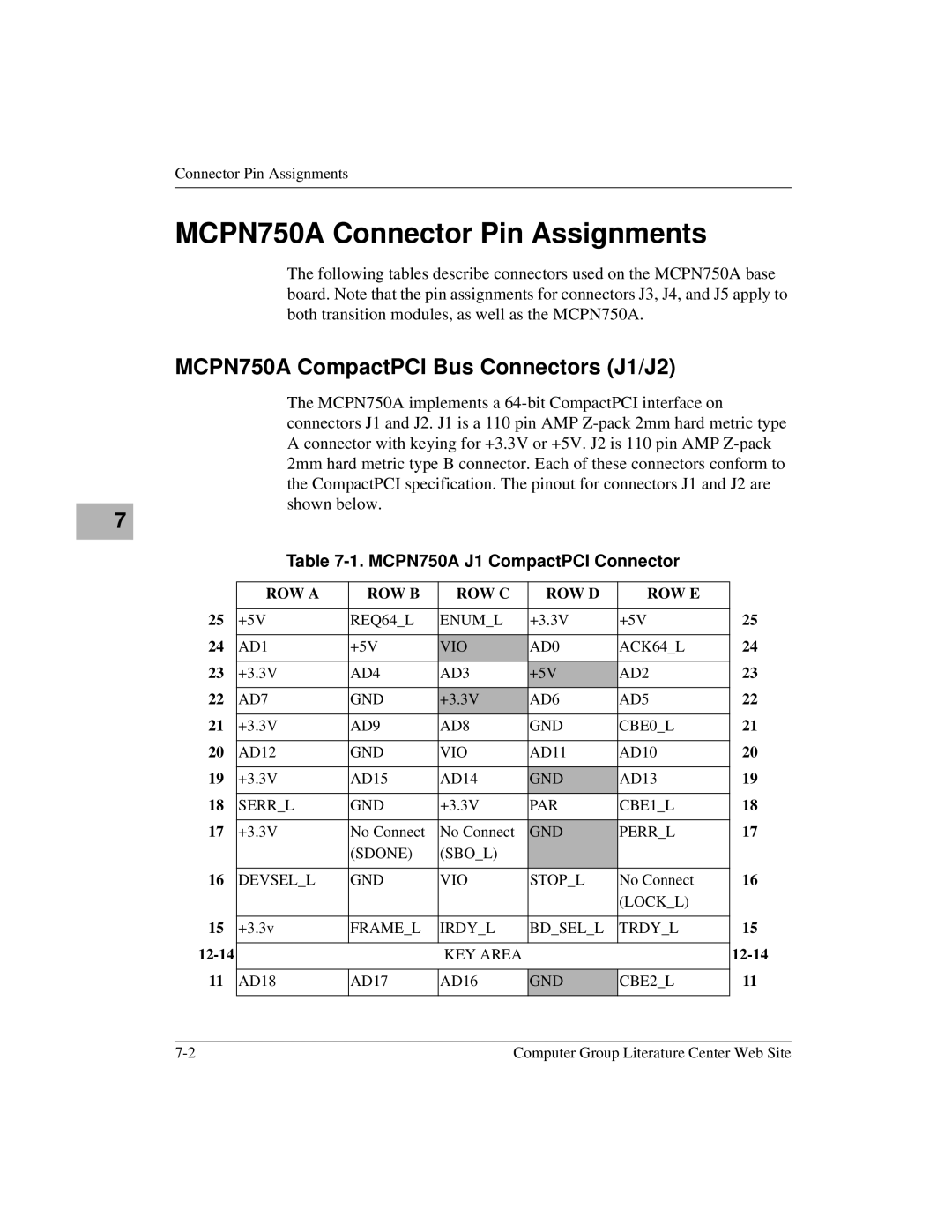
MCPN750A Connector Pin Assignments
The following tables describe connectors used on the MCPN750A base board. Note that the pin assignments for connectors J3, J4, and J5 apply to both transition modules, as well as the MCPN750A.
MCPN750A CompactPCI Bus Connectors (J1/J2)
The MCPN750A implements a
Table 7-1. MCPN750A J1 CompactPCI Connector
| ROW A | ROW B | ROW C | ROW D | ROW E |
|
25 |
|
|
|
|
| 25 |
+5V | REQ64_L | ENUM_L | +3.3V | +5V | ||
24 |
|
|
|
|
| 24 |
AD1 | +5V | VIO | AD0 | ACK64_L | ||
23 |
|
|
|
|
| 23 |
+3.3V | AD4 | AD3 | +5V | AD2 | ||
22 |
|
|
|
|
| 22 |
AD7 | GND | +3.3V | AD6 | AD5 | ||
21 |
|
|
|
|
| 21 |
+3.3V | AD9 | AD8 | GND | CBE0_L | ||
20 |
|
|
|
|
| 20 |
AD12 | GND | VIO | AD11 | AD10 | ||
19 |
|
|
|
|
| 19 |
+3.3V | AD15 | AD14 | GND | AD13 | ||
18 |
|
|
|
|
| 18 |
SERR_L | GND | +3.3V | PAR | CBE1_L | ||
17 |
|
|
|
|
| 17 |
+3.3V | No Connect | No Connect | GND | PERR_L | ||
|
| (SDONE) | (SBO_L) |
|
|
|
16 |
|
|
|
|
| 16 |
DEVSEL_L | GND | VIO | STOP_L | No Connect | ||
|
|
|
|
| (LOCK_L) |
|
15 |
|
|
|
|
| 15 |
+3.3v | FRAME_L | IRDY_L | BD_SEL_L | TRDY_L | ||
|
|
|
|
| ||
|
| KEY AREA |
|
| ||
11 |
|
|
|
|
| 11 |
AD18 | AD17 | AD16 | GND | CBE2_L | ||
|
|
|
|
|
|
|
Computer Group Literature Center Web Site |