There are two pairs of
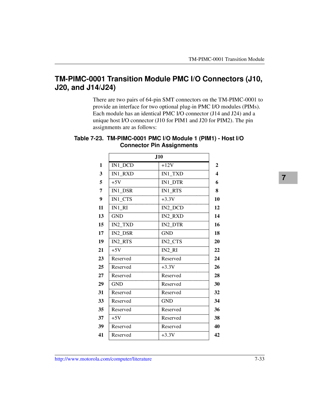
Table
Connector Pin Assignments
|
| J10 |
| |
1 |
|
|
| 2 |
IN1_DCD |
| +12V | ||
3 |
|
|
| 4 |
IN1_RXD |
| IN1_TXD | ||
5 |
|
|
| 6 |
+5V |
| IN1_DTR | ||
7 |
|
|
| 8 |
IN1_DSR |
| IN1_RTS | ||
9 |
|
|
| 10 |
IN1_CTS |
| +3.3V | ||
11 |
|
|
| 12 |
IN1_RI |
| IN2_DCD | ||
13 |
|
|
| 14 |
GND |
| IN2_RXD | ||
15 |
|
|
| 16 |
IN2_TXD |
| IN2_DTR | ||
17 |
|
|
| 18 |
IN2_DSR |
| GND | ||
19 |
|
|
| 20 |
IN2_RTS |
| IN2_CTS | ||
21 |
|
|
| 22 |
+5V |
| IN2_RI | ||
23 |
|
|
| 24 |
Reserved |
| Reserved | ||
25 |
|
|
| 26 |
Reserved |
| +3.3V | ||
27 |
|
|
| 28 |
Reserved |
| Reserved | ||
29 |
|
|
| 30 |
GND |
| Reserved | ||
31 |
|
|
| 32 |
Reserved |
| Reserved | ||
33 |
|
|
| 34 |
Reserved |
| GND | ||
35 |
|
|
| 36 |
Reserved |
| Reserved | ||
37 |
|
|
| 38 |
+5V |
| Reserved | ||
39 |
|
|
| 40 |
Reserved |
| Reserved | ||
41 |
|
|
| 42 |
Reserved |
| +3.3V | ||
|
|
|
|
|
7 |
http://www.motorola.com/computer/literature |